I'M Trying to understand and applying that.
could be that the right way?
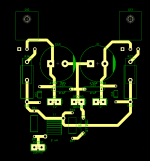
I was suggesting something like this. High current traces would be changed to planes.
Attachments
Last edited:
That on its own brings a dirty ground from speaker return and zobel next to sensitive circuits like the input stages ...
very common mistake ...
My earlier post says return speaker grounds to the supply, not the amplifier.
You didn't read my post completely. Very common mistake. How about providing an example. You keep telling us how wonderful you are at it, but never show anything to back it up.
Member
Joined 2009
Paid Member
If you think about where signal currents flow and where dc flows and where ripple current flows you will understand the reasoning behind Sakis comments - e.g. speaker gnd return goes to rail cap near output power devices, not back to power supply, only dc through speaker will show up at trafo center tap. Calling every node at nominal zero volts a ground doesn't help make things clear I'm afraid.
Last edited:
If you think about where signal currents flow and where dc flows and where ripple current flows you will understand the reasoning behind Sakis comments - e.g. speaker gnd return goes to rail cap near output power devices, not back to power supply, only dc through speaker will show up at trafo center tap. Calling every node at nominal zero volts a ground doesn't help make things clear I'm afraid.
As I said earlier, there are many theories on this. Everyone providing a theory is correct in their own mind. I just go with what the general agreement is with most of the people willing to give some actual helpful examples. The three people I listen most closely too are AndrewT, Ostripper and VZaichenko. All three agree that speaker returns should go to the main supply star ground as far as I'm aware.
Ground carries loads of dirty products , produced by the combination of type of load , speaker cable zobel and so on
You don't want this ground close to your LTP many designers use a clean ground through a resistor to provide a cleaner ground to the stages of the amplifier that needed
Farther more that is one of the reasons that you don't want your ground twisted with the rails Obviously at some point of the operation the one will eventually modulate the other and that will create catastrophic feedback
Think out of the box Why designers often use regulated supplies for the first stages often above rail voltage ?
1) because they need the cleanest available
2) due to softer clipping reasons
So yes making sure that all conditions are clean as possible at your input stages is mandatory ...
Now AndrewT's rails and main psu are simulated ( in a way ) so these are perfect and will never be modulated by the load or the amplifier it self or the induction of the combination specific music program ,amplifier board , hardware , cable , speaker ....
That is not truth ...Just wire 10 rounds of cable to any of the rail cables of a playing amplifier , connect a small speaker or headphone on the edges and you will listen to music ...so rails are modulated end of story ....
Now as about the triplet and the ground you may add conditions that in Andrew's home town take as a fact that common or 0V of the amplifier is to be connected to the safety ground earth of the amplifier ... In my home we follow the option of professional amplifiers and like to keep 0V or audio ground of the audio signal at ground lift condition floating or separated name it any way you like it ...
This is the cleanest way to go ...Imagine what will happen if you live in Andrew's home town and beyond local products that you have included in your ground scheme and the triplet you have to add some other products like Noise EMI and so on that might exist in your home ground ...
Please no hard feelings Andrew i have nothing but respect in the depth of your knowledge and your will to correct our mistakes Only because some times you are pretty stiff about a few things and you take things for granted i enjoy to tease you mend to be as a joke ....
To close my argument i can post like 1500 pics from consumer amps and in NO one you will ever see the ground inside the twist ...
Kindest regards with a touch of humor
Sakis
Last edited:
I know that I have to repeat myself.Andrew you have commented that in the past check you own writing
Members don't bother doing much research for their own project.
I know that I have to repeat myself.
Members don't bother doing much research for their own project.
Yes Andrew that is very correct ...
Let us not forget what said from a legend of the forum that classic EF2 amplifiers are very forgiving and tolerant to many of the mistakes designer or diyers do
If I understood this I might agree.Ground carries loads of dirty products , produced by the combination of type of load , speaker cable zobel and so on
You don't want this ground close to your LTP many designers use a clean ground through a resistor to provide a cleaner ground to the stages of the amplifier that needed
Farther more that is one of the reasons that you don't want your ground twisted with the rails Obviously at some point of the operation the one will eventually modulate the other and that will create catastrophic feedback
Think out of the box Why designers often use regulated supplies for the first stages often above rail voltage ?
1) because they need the cleanest available
2) due to softer clipping reasons
So yes making sure that all conditions are clean as possible at your input stages is mandatory ...
Now AndrewT's rails and main psu are simulated ( in a way ) so these are perfect and will never be modulated by the load or the amplifier it self or the induction of the combination specific music program ,amplifier board , hardware , cable , speaker ....
That is not truth ...Just wire 10 rounds of cable to any of the rail cables of a playing amplifier , connect a small speaker or headphone on the edges and you will listen to music ...so rails are modulated end of story ....
Now as about the triplet and the ground you may add conditions that in Andrew's home town take as a fact that common or 0V of the amplifier is to be connected to the safety ground earth of the amplifier ... In my home we follow the option of professional amplifiers and like to keep 0V or audio ground of the audio signal at ground lift condition floating or separated name it any way you like it ...
This is the cleanest way to go ...Imagine what will happen if you live in Andrew's home town and beyond local products that you have included in your ground scheme and the triplet you have to add some other products like Noise EMI and so on that might exist in your home ground ...
Please no hard feelings Andrew i have nothing but respect in the depth of your knowledge and your will to correct our mistakes Only because some times you are pretty stiff about a few things and you take things for granted i enjoy to tease you mend to be as a joke ....
To close my argument i can post like 1500 pics from consumer amps and in NO one you will ever see the ground inside the twist ...
Kindest regards with a touch of humor
Sakis
But the examples are so convoluted that I can't follow what you are suggesting is right and wrong.
I have applied Andrew's advice on grounding and minimisation of high current loop areas on my projects and have observed less noise residual on the scope trace and in practice with my ear to the tweeter. I don't usually bother with ground lifts anymore - they are not required and can even prove detrimental when the layout is optimised.
Sakis, thank you for providing some information that can be used by all. This is much more useful than just telling everyone they are wrong!
I agree, the LTP and the whole input stage require a silent ground. Many, including myself are using a separate ground wire to the input stage from the supply star ground.
In my experience, AndrewT's suggestion of twisting speaker out and return does seem to lower noise emission of the output wiring, but there's always room for more properly explained theories on this. I also achieve very good results with the twisted triplet of power supply to the amplifier itself. How would you suggest to feed them in the quietest way possible?
I have applied Andrew's advice on grounding and minimisation of high current loop areas on my projects and have observed less noise residual on the scope trace and in practice with my ear to the tweeter. I don't usually bother with ground lifts anymore - they are not required and can even prove detrimental when the layout is optimised.
Exactly like high quality 99999% clean sliver but not shielded diy phono interconnect cables made by diyers
...they play marvelous only parameter though to make them play is to operate them in a sterilized environment from general EMI aspects ...
Exactly like high quality 99999% clean sliver but not shielded diy phono interconnect cables made by diyers
...they play marvelous only parameter though to make them play is to operate them in a sterilized environment from general EMI aspects ...
Hi East
I've never used silver wire or other "esoteric" components or materials but I do tend to use shielded interconnect (internal and external of the chassis) for small signal transfer.
I like to position the transformer so that it has a large air gap between it and the RCA inputs, signal wiring and other sensitive components. I generally try to use the (grounded) heat-sink as a shield between the transformer and the amplifier circuit.
To explain farther in a few words i have to post my PCB I promised not to do that ...
Think out of the box keep heat sinking out of the picture and design like output transistors do not heat sink ...Then you will solve most of the problems
After that you will need to find out how to cool the outputs ......far easier
Think out of the box keep heat sinking out of the picture and design like output transistors do not heat sink ...Then you will solve most of the problems
After that you will need to find out how to cool the outputs ......far easier
I wonder,what we share here?Producing a PCB for P3A more than 5 years ago ,starting from designs like the ones presented above and advancing from there while evaluating these little small details from one pcb to another which means more than 15 versions of pcb on a given design ( as was in the original circuit) took about 3 years of work and countless hours in front of a scope and a spectrum analyzer .
In most of my comments i try to give guidelines and help others to think alike but i am not willing to share for free 3 years of work ....
By the way this could be done for any given amplifier it just happened that beyond others i liked the sound of P3A as was in the first place next to many others ...
Kind regards
Sakis
I wonder,what we share here?
I'm wondering the same.
Check my posts thimios thousands and thousands of posts helping people in repairs and troubleshooting ...some things though i like to keep for personal amusement ...
I have seen that you have been constructing many things ...Nice ...I could never do that ...I choose one of the amplifiers that i liked and start to work only with this since 2006 when i first listened to a P3A in a vero board ...
Do the same in any of your amplifiers and then get back to us ...
I have seen that you have been constructing many things ...Nice ...I could never do that ...I choose one of the amplifiers that i liked and start to work only with this since 2006 when i first listened to a P3A in a vero board ...
Do the same in any of your amplifiers and then get back to us ...
To explain farther in a few words i have to post my PCB I promised not to do that ...
Think out of the box keep heat sinking out of the picture and design like output transistors do not heat sink ...Then you will solve most of the problems
After that you will need to find out how to cool the outputs ......far easier
As you said, these guidelines apply to all amps. A suggested layout for any output would be helpful. A picture's worth a thousand words. A thousand words is worth nothing if nobody can figure out what you are saying.
- Status
- This old topic is closed. If you want to reopen this topic, contact a moderator using the "Report Post" button.
- Home
- Amplifiers
- Solid State
- P3A layout