upc1237 short circuit overload
ãÏÇÑ ãÍÇÝÙ Çã�áí ÝÇíÑ ˜Çãá (ãÍÇÝÙ DC , ÊÇÎíÑ , ÇÊÕÇá ˜æÊÇå æ...)
Maybe this is useful
warm regards
Andrew")
ãÏÇÑ ãÍÇÝÙ Çã�áí ÝÇíÑ ˜Çãá (ãÍÇÝÙ DC , ÊÇÎíÑ , ÇÊÕÇá ˜æÊÇå æ...)
Maybe this is useful
warm regards
Andrew
Attachments
How does this works, anyway?
Hello,
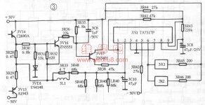
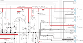
I am wondering if I am wrong but those schematic, and all those overcurrent protectors would work OFF/ON/OFF/ON/OFF... infinitly while amp output terminal are shorted and output ac signal is high enough to make voltage drop on Re resistor to make sesning transistor conducting?
When load is connected to amp output voltage on Re wont get high enough to make sensing transistor conducting and relay on upc1237 wont broke off. When output is shorted (or small impedance connected) and output ac signal is high enough, relay of upc1237 will broke off, and disconnect shorted output line, and Re voltage would become small enough to make relay broke off again, and the proces would be OFF/ON/OFF/ON/OFF/ON...
Am I right ?
Hello,
I am wondering if I am wrong but those schematic, and all those overcurrent protectors would work OFF/ON/OFF/ON/OFF... infinitly while amp output terminal are shorted and output ac signal is high enough to make voltage drop on Re resistor to make sesning transistor conducting?
When load is connected to amp output voltage on Re wont get high enough to make sensing transistor conducting and relay on upc1237 wont broke off. When output is shorted (or small impedance connected) and output ac signal is high enough, relay of upc1237 will broke off, and disconnect shorted output line, and Re voltage would become small enough to make relay broke off again, and the proces would be OFF/ON/OFF/ON/OFF/ON...
Am I right ?
Three schemes that you have shown - it is more appropriate to correct circuit.
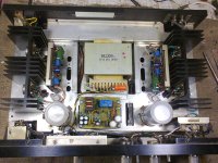
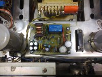
I have recently restored an old amplifier Sansui BA150. Protection scheme
created his own without the use of the chip. I like that better.
I have recently restored an old amplifier Sansui BA150. Protection scheme
created his own without the use of the chip. I like that better.
Attachments
Andreas, is this your own protection or Sansui own? Sansui was using BC transistors?
Anyway, I am not sure how is this circuit works but it looks like it needs 0.7V+0.7V+0.7V for VT4 to make it conductive, so 2.1V. And the logic is the same, right? It needs to feel voltage drops to make relay broke off?
I am trying to say this:
1. Output load connected-relay on
2. Output shored - relay off (when relay off, voltage drops down and relay on, when relay on, voltage drops rise and relay off, etc, etc... so it is repetitive on/off/on/off?)
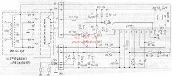
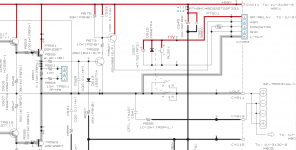
Here is also protection schematic of Denon PMA-2000 implemented via thyristor:
Anyway, I am not sure how is this circuit works but it looks like it needs 0.7V+0.7V+0.7V for VT4 to make it conductive, so 2.1V. And the logic is the same, right? It needs to feel voltage drops to make relay broke off?
I am trying to say this:
1. Output load connected-relay on
2. Output shored - relay off (when relay off, voltage drops down and relay on, when relay on, voltage drops rise and relay off, etc, etc... so it is repetitive on/off/on/off?)
Here is also protection schematic of Denon PMA-2000 implemented via thyristor:
Attachments
Greetings Kunalagon.Hello,
I am wondering if I am wrong but those schematic, and all those overcurrent protectors would work OFF/ON/OFF/ON/OFF... infinitly while amp output terminal are shorted and output ac signal is high enough to make voltage drop on Re resistor to make sesning transistor conducting?
When load is connected to amp output voltage on Re wont get high enough to make sensing transistor conducting and relay on upc1237 wont broke off. When output is shorted (or small impedance connected) and output ac signal is high enough, relay of upc1237 will broke off, and disconnect shorted output line, and Re voltage would become small enough to make relay broke off again, and the proces would be OFF/ON/OFF/ON/OFF/ON...
Am I right ?
Yes, that's right, the time interval is off delay time when the amplifier.
It's ugly, but it will give the user know that there is a fault or short circuit. There is also the trigger and protection schemes - after a trip switch is only possible after the power amplifier.
Yes, this is my own design of the amplifier. In Sansui BA150 primitive circuit protection, fuse ... and DC sensor that is triggered thyristors output circuit.Andreas, is this your own protection or Sansui own? Sansui was using BC transistors?
Scheme for Sansui VA150 I could not find, so using a circuit end portion Sansui AU999 - they are identical.
No, not true, the circuit is triggered when output short circuit when the voltage across the resistor emitter of the output transistor reaches 0.7V.Anyway, I am not sure how is this circuit works but it looks like it needs 0.7V+0.7V+0.7V for VT4 to make it conductive, so 2.1V. And the logic is the same, right? It needs to feel voltage drops to make relay broke off?
When there is no output short circuit, the threshold increase - operates a chain of R3 D1. Together with the R2 forms a divider.
Yes, that's right,I am trying to say this:
1. Output load connected-relay on
2. Output shored - relay off (when relay off, voltage drops down and relay on, when relay on, voltage drops rise and relay off, etc, etc... so it is repetitive on/off/on/off?)
Here is also protection schematic of Denon PMA-2000 implemented via thyristor:
1 - in short circuit mode amplifier does not spoil, but the user will know the fault load and must be eliminated.
2 - if the input signal is so high or low the user to connect the load - the amplifier will also be cyclically switched off. If you make less volume - again amplifier will work as usual.
But Denon have to turn off / on, it's uncomfortable.
In my circuit is very simple to build latch mode and it will work as Denon.
Yes.Thank you Andreas. That is all I need to know. And I see upc1237 have latching function, so it is possible to use it by connecting capacitor between pin 3 and gnd, and then IC needs power off to reset relay
Andreas till how many watts this protection for very nice of you for helping out
warm regards
Andrew
The maximum output power of 50W, 4 ohms. Resistor in the emitter of the output transistor 0.47ohms.
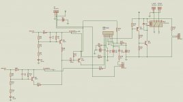
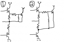
I don't like to stir up old threads but all the overload protection circuits minus one of them use only the positive transistor to sense the output current. For an example please look at my (sorry in advance) cruelly drawn picture.
Wouldn't circuit 2 be better to use because if the negative transistor overloads then the protection will trip and if the positive overloads the protection will trip?
Wouldn't circuit 2 be better to use because if the negative transistor overloads then the protection will trip and if the positive overloads the protection will trip?
Attachments
Agreed. When SOA (or VI) limiter circuits are used, the amplifier remains operational and the limiting action is clamping the output continuously at the speed of the signal. You do need to monitor both sides of the output stage for the purpose there.
An overload protection device is a little different in that it often only monitors current and works as a latching switch. Speed is limited by the relay drop-out time but it only has to sense a high current arising from the audio signal once, from either polarity, to remove power to the output relay. It may then latch or delay reset to prevent erratic cycling.
A Mosfet output protection switch is a much better proposition for really fast output protection. These can also offer better protection by responding to faults on either side of the output stage fast enough. DIYs though, don't seem be interested in using them - probably not an Ebay toy yet
Well here is my situation, but first a little specs-
The amp is called "The Beast" and I made it off a modified pioneer spec 2/4 amp circuit. I modded the circuit in numerous ways combining the best of the two amps. Now The Beast is rated (haven't tested it yet) up to 1000 watts per channel, has a total of 32 output transistors (8+8 CH1 8+8 CH2) and is push pull type output, as you saw above. The one thing is that I HATE, absolutely despise are VI limiters... so for this reason I took them out- see why I want to measure both the positive and negative outputs now?
The emitter resistors are .22 ohm, but may be upgraded to .47 or even as high as 1 ohm....
So here's kinda what I want to do- the amplifier is rated for 1000 watts per channel. I want the limiters to trip at around 1200W which is ample headroom to play comfortably at 1KW. This is the only protection the amplifier has to protect it from over current, but what I found out afterwards is that it is not the first.
There is a whole series of amplifiers in Sony lineup- Old powerful amps that actually used two UPC1237 chips. One would control the speaker protection, with an overload detection while another did something I found to be interesting. The main voltage supply had a high voltage and a low voltage which was controlled by the second UPC1237- When the amp hit a certain current value I guess it would trip to the low supply rail... If I find it, I will tell you the amp series this was used in, or just send a pic.
So for me to get this to protect the amplifier, It would truly be better if I monitored the two sides, correct?
Thanks for a fast response here!
This is a very powerful amplifier.Well here is my situation, but first a little specs-
The amp is called "The Beast" and I made it off a modified pioneer spec 2/4 amp circuit. I modded the circuit in numerous ways combining the best of the two amps. Now The Beast is rated (haven't tested it yet) up to 1000 watts per channel, has a total of 32 output transistors (8+8 CH1 8+8 CH2) and is push pull type output, as you saw above. The one thing is that I HATE, absolutely despise are VI limiters... so for this reason I took them out- see why I want to measure both the positive and negative outputs now?
The emitter resistors are .22 ohm, but may be upgraded to .47 or even as high as 1 ohm....
So here's kinda what I want to do- the amplifier is rated for 1000 watts per channel. I want the limiters to trip at around 1200W which is ample headroom to play comfortably at 1KW. This is the only protection the amplifier has to protect it from over current, but what I found out afterwards is that it is not the first.
There is a whole series of amplifiers in Sony lineup- Old powerful amps that actually used two UPC1237 chips. One would control the speaker protection, with an overload detection while another did something I found to be interesting. The main voltage supply had a high voltage and a low voltage which was controlled by the second UPC1237- When the amp hit a certain current value I guess it would trip to the low supply rail... If I find it, I will tell you the amp series this was used in, or just send a pic.
So for me to get this to protect the amplifier, It would truly be better if I monitored the two sides, correct?
Thanks for a fast response here!
protection function I would divide into three points.
1 short circuit
2nd current limit
3- protection speakers.
1 short-circuit always works the same way - the sensor measures the resistor current output transistor emitter.
2 current limit - Current measurement in the normal way of limitation.
3 - External control current limiting - so the speaker protection.
- Home
- Amplifiers
- Solid State
- Overload detection circuit for UPC1237