but his model predicts different results.I looked over the work of David Eather's and he is basically saying the exact same thing
You make your designer's/engineer's choice, 30/45/60 degrees of phase load. It's much more important that you make informed decisions than just grab at numbers.
If reliability is truly a concern, then just increase the output
pairs untill the OPS works far from the limiting curves...
SOA is a concern only for those willing to squeeze the hell
out of OPS while staying marginally in safe area, generaly
for budget reasons, mainly a manufacturer concern,i.e
optimizing the components cost....
Are we just blattering about a few $ of devices, while the
rest of the amp makes for 95% of the total cost?...
AndrewT,
I tried to go back and look at his articles again but I can't find them. As I said before I believe that the major difference between my formula and his is phase shift angle. I believe that the phase shift is mostly resistive with the inductive component being much smaller. If you use 45* or 60* phase shift you will need more devices. My experience tells me that 30* works fine with both active and passive speaker loads. At my company we designed and manufactured thousands of Soundstream car and home audio and Stewart Electronics pro audio power amplifiers all designed around the 30* phase shift. Our line of pro audio amplifiers actually won a TEC award at the 1994 AES convention. I would like to see the articles by David again. How much difference have you noted.
I tried to go back and look at his articles again but I can't find them. As I said before I believe that the major difference between my formula and his is phase shift angle. I believe that the phase shift is mostly resistive with the inductive component being much smaller. If you use 45* or 60* phase shift you will need more devices. My experience tells me that 30* works fine with both active and passive speaker loads. At my company we designed and manufactured thousands of Soundstream car and home audio and Stewart Electronics pro audio power amplifiers all designed around the 30* phase shift. Our line of pro audio amplifiers actually won a TEC award at the 1994 AES convention. I would like to see the articles by David again. How much difference have you noted.
What do you guys think of this?
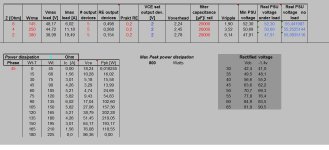
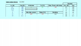
I attached some pictures from mine spreadsheet.
Input:
145W/8Ohm
250W/4Ohm
==> transfo of 40V 0 40V
Phase of load 45°
Temperature output devices 50°C.
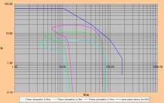
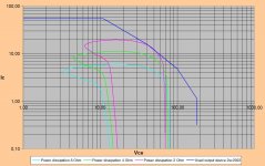
Output:
SOA curve with 4 devices
SOA curve with 5 devices
It seems that 4 devices will fail.
Am I to conservative. I know that a speaker at certain frequencies can have a real low impedance and a big phase shift.
I have laying around 16x 2SC2922Y and 16x 2SA1216Y, but its not my intention to use to much of them if not really needed.
I attached some pictures from mine spreadsheet.
Input:
145W/8Ohm
250W/4Ohm
==> transfo of 40V 0 40V
Phase of load 45°
Temperature output devices 50°C.
Output:
SOA curve with 4 devices
SOA curve with 5 devices
It seems that 4 devices will fail.
Am I to conservative. I know that a speaker at certain frequencies can have a real low impedance and a big phase shift.
I have laying around 16x 2SC2922Y and 16x 2SA1216Y, but its not my intention to use to much of them if not really needed.
Attachments
Last edited:
And I beleive that those small "destroyed" spots cause the transistor to have leakage as we saw in the ADCOM repair thread.
Yup, locally the diffusion atoms migrate as the temp gets too high, sometimes you will get three or more patches destroyed while the rest of the die in undamaged, but without specialist equipment you would never be able to prove it.
The most spectacular failure, not second breakdown though, I saw was a very high voltage TO3 device that had failed on the production line at the VCEO test, ~1.4KV spark jumped from case to lead and burnt a hole in the tophat... my own personal guess is that the bond wire was too slack and came a bit close to the case and corona discharge allowed the high voltage supply to do the rest.
Wrinkle
My experience tells me that 30* works fine with both active and passive speaker loads. At my company we designed and manufactured thousands of Soundstream car and home audio and Stewart Electronics pro audio power amplifiers all designed around the 30* phase shift. Our line of pro audio amplifiers actually won a TEC award at the 1994 AES convention. I would like to see the articles by David again. How much difference have you noted.
I reckon designing for a 4ohm 60 degree load accomodates at least 99% of loudspeakers on the market.
The same approach, only different sw used:
Pavel, how did you plot your SOA curves and reactive load lines in SPICE?
I also did mine in spice - allows very quick checking. I will have to try to dig mine out.
I'd still be interested to see this
")
- Status
- This old topic is closed. If you want to reopen this topic, contact a moderator using the "Report Post" button.
- Home
- Amplifiers
- Solid State
- Output transistor safe operating area