Talk to me about theory. 2 bass units and $270 later.
PMA I assume you are also switching the speaker gnd return? I did some sims FWIW and got 8ppm with 8 ohm load. Switches are in GND return and therefore outside the feedback loop. (I just measured the distortion a across the MOSFET pair). Since this is the distortion just across the mos pair it is in fact Much lower reference the output signal.
PMA I assume you are also switching the speaker gnd return? I did some sims FWIW and got 8ppm with 8 ohm load. Switches are in GND return and therefore outside the feedback loop. (I just measured the distortion a across the MOSFET pair). Since this is the distortion just across the mos pair it is in fact Much lower reference the output signal.
Last edited:
Talk to me about theory. 2 bass units and $270 later.
At least you have been able to get them... price doesn't come as a surprise tbh.
Here's what I use - simple, reliable, easily scalable, and quiet.
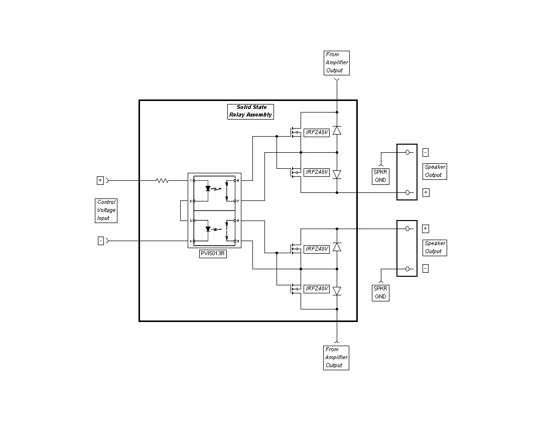
where does the two inputs on the left connect to?
Hi Digits,
Yes, as Bonsai says, the terminals labeled "control voltage input" are where a mechanical relay coil would be connected, usually to an existing protection circuit. Obviously, you'll need to know the voltage and calculate the resistor to provide at least 5ma current to the LEDs, I use 10ma as best compromise. To calculate required resistance, subtract the total voltage drop across the LEDs, nominal 1.2 volts each, from the available drive voltage and divide by .01(10ma). For example, if nominal drive voltage is 12 volts, calulation would be: 12v-2.4v=9.6v, 9.6v/.01=960 ohms. So resistor value of 910 ohms to 1k ohm would be OK. And be mindful of proper polarity or it won't work.
Mike
Hi, I just tested two irf540, posted circuit without the two diodes.
@ 3.35Adc (from a Lab supply set to 800mVdc) the Vdrop across Source to Drain is 102mVdc and 104mVdc for the other.
I used a sig gen set to sq wave and offset to output +8.5Vdc to +0.02Vdc and applied these to the D-G terminals. No heatsinks.
Tried a range of frequencies from 1 cycle per 2minutes upto 3cycles per ms.
~.01Hz to ~3kHz while still passing that lab supply 3.35Adc. And it works in the opposite polarity. The gate drive does not turn on with opposite polarity.
Hi Andrew T,
I've been using it for years, works like a charm. But be aware, gate drive must be floating, that's why I suggested testing it using 9volt battery, and also why I chose to use the photvoltaic optoisolator in the final design. It's simple, elegant and easy to do.
Mike
I've been using it for years, works like a charm. But be aware, gate drive must be floating, that's why I suggested testing it using 9volt battery, and also why I chose to use the photvoltaic optoisolator in the final design. It's simple, elegant and easy to do.
Mike
Hi,
What about using a PTC Resettable Fuses in the output to the speaker. It will open if the current is too high. I do not know what will do to the sound but is a cheap solution. I never try it since my amplifiers are Dynaco 120 with a speaker coupling capacitor.
Regards,
tauro0221
What about using a PTC Resettable Fuses in the output to the speaker. It will open if the current is too high. I do not know what will do to the sound but is a cheap solution. I never try it since my amplifiers are Dynaco 120 with a speaker coupling capacitor.
Regards,
tauro0221
Hi Tauro0221,
I don't like that idea for a couple of reasons. First, PTC thermistor will be too slow to offer any real protection, and second, it will definitly distort the signal, they're inherently non-linear devices. Like Mr. Einstein said; "Things should be as simple as possible, but no simpler." So no, in my opinion, not a good idea. Sorry.
Mike
Hi,
What about using a PTC Resettable Fuses in the output to the speaker. It will open if the current is too high.
I use PTCs in industrial applications in order to meet UL standards for fire safety. The PTC I use has a hold current of 7A (so it could be a likely candidate for speaker protection) and trips at 15A. It takes 23s at 15A before it trips. This is at 25 degrees Celsius. If the unit is colder then it will take longer. This behaviour is good enough to prevent the factory from burning done but the unit is generally a lump of warm charcoal by then... so I would not recommend them if your intention is to protect a speaker. Your lounge will be safer though...
The International Rectifier photovoltaic isolators may seem slow but remember that a relay will open/close in the 100ms range - especially if you have added a diode to protect the transistor switch form back emf.
Dear Tommy1000
It is because of the unlinear resistance of the relay as a function of current through it, the distortion was like -60dB.
Using relays for input selection also presents a problem, very few relays are specified for use with very small currents.
Using a rotary switch with good contact pressure is much preferred.
Regards
Vitreus.
Still a bit OT, but I wanted to correct this as it is misleading (polite for "not true"!)
MANY relays are specified for very small currents. The Automatic testing industry (ATE) uses many millions of them.
Miniature reed relays will exhibit 50mR (.05R) contact resistance +/- 5% over a lifetime of billions of operations. That resistance is actually bulk resistance of the reed blades, not the surface contact resistance.
Chose your relay technology: ATE, telecomms etc all use them to great effect.
OK here's what we've heard so far....
1) Relays not so good. Potential for contact welding in fault conditions. Alternate relay recommendations include large bulky automotive/truck relays.
2) MOSFETs in series. Works, need isolated gate drive. RDSon in order of tens of milliohms.
3) PTC or polyswitches - ridiculous. You don't want anything more than a simple conductor in your high power signal path.
4) What about this?
http://www.allegromicro.com/en/Products/Part_Numbers/0756/0756.pdf
130 micro (yes micro) ohm current sense element. Isolated, no voltage swing limitations, high current capability.
Take its output, monitor it and use it to take down the AC soft-start relay. Then you'll have no relays in the signal path.
You could put the PTC inside the negative feedback loop with the necessary circuitry to ensure the amp behaves when it opens (see Cordellfor inspiration).
On the gatedrive, if you put the mosfet switches om the ground return line, you can drive aback to back pair ok. I will try to post up something a bit later today. The are 100V mosfets that do 4 m Ohm now and 200V devices that will do sub 10mO.
Still another approach here will be to switch the supply rails to the amplifier. So, retail the normal relay switching for muting etc, but use rail switching for protection on catastrophic failure.
I am leaning toward just a ground referenced MOSFET switch arrangement at the minute.
Good discussion and some great ideas BTW!
- Home
- Amplifiers
- Solid State
- Output Relays