mjl or njw X302/281's have about 2X the Hfe as their X21193/4 counterparts. They don't push the limits on the mje's/properly heatsinked. If I used 6 or more pairs , I would go with the OP's as drivers. 21193/4's are at best 50Hfe (often less) , 3 pair drawing up to .5A @ 2-4R. The mje's are at best 300ma @ 75v soa.
Some on the forum will "pile" up a dozen OP pairs on a EF2 w/mje's - bad . Not I.... Electrically , njw0281/0302 is identical to the mje's , just a bigger die - a bit more Cob.
You are fine as is , but if you build a new amp - why not ?
Some on the forum will "pile" up a dozen OP pairs on a EF2 w/mje's - bad
. Not I.... Electrically , njw0281/0302 is identical to the mje's , just a bigger die - a bit more Cob.You are fine as is , but if you build a new amp - why not ?
Last edited:
Well - SSR is almost perfect, when properly designed. Standard relay is almost incapable to interrupt high current DC arc, that may occur in a high power amplifier. And, even if it succeeds, you have to change it after 1st interruption
WOW -
simple. Looks like some of the opto-coupled big industrial SS AC switches I've seen. 3uS turnoff - 100's of ac volts. .01R Rdson !ASSR-1611 (halfway down the page) - ASSR-1611 datasheet, Pinout ,application circuits High Current, 1 Form A, Solid State Relay (MOSFET).
That's a small one - 30-60A units run $100usd and up.
Would be much cheaper to build one.
OS
Last edited:
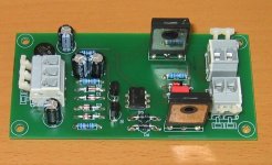
As you have guessed, I speak about the built circuit.
Attached.
I can reverse engineer that by just seeing it - just kidding (the SS relays are essentially the same circuit minus the DC detect).
No heatsink ? With super low RDSon not needed ?
I was thinking a tda-xxxx protection IC triggering opto X2 (stereo) ... much better than contacts .. regardless.
OS
Here's what I use - simple, reliable, easily scalable, and quiet.
What about the steering diode voltage drop and the minimum photo detector supply voltage requirement. Looks like a very distorted solution for Audio use ?
Auto (car) relays work flawlessly (for a few years anyway) in a hostile DC environment.
It's easy to obtain 16A - 30A auto relays which are great for speaker protection.
Sorry for the double post - my internet connection is playing up - some bugger riding on the wireless connection I expect.
Which is why I said, generaly. Just like ordinary switches, there are ones designed to switch DC, normally at lowish potentials, the downside is the costs.
The problem here is how to handle a clean relay switch over with 75 or so volts across the contacts and in my case about 6 ohms DC resistance. I took the relay out last night and opened it up. The contacts are truly welded together. I stuck a screw driver between the contact surfaces to try to pry them apart. No chance. I've taken a long hard look at this over the last few days and if you want your relay to be able to handle the worst case 'up to your *** in alligators' problem, you really need a good relay.
I looked at the auto relay but they are spec'd for 13.5V and from what I've seen the relay DC specs, the current capability drops off quickly as contact voltage goes up. The Panasonic relays I referred to in my first post look pretty good. Single contact set rated to switch 10 at 100V. They also spec the relay for higher current switching, but with a reduced life.
I have at several occasions here mentioned the special audio relay from Amplimo. It has two contacts: a tungsten 100A contact and silver/gold contact.
When it closes, first the tungsten closes and then the silver/gold one to make the resistance almost zero. When opening, first the silver/gold opens and then the tungsten.
Of course, they are not cheap; last time I looked almost 7 euro each!
jan didden
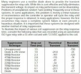
Speaking of welding relay contacts together, you should read this article on relay coil suppression techniques. If you just use a rectifier diode to suppress the transient you will slow down the release of the armature which can result in welded contacts.
Whole article.
http://relays.tycoelectronics.com/appnotes/app_pdfs/13c3311.pdf
Excerpt.
Whole article.
http://relays.tycoelectronics.com/appnotes/app_pdfs/13c3311.pdf
Excerpt.
Attachments
Switching the rails with power hexfets and Hall effect current sensors is a pretty smart alternative, imo, as Goldmund does in the Telos 600/1000 series (Honeywell CSN series and IRFP260).
For BJT output stages, it could be combined with shunting the output to ground.
(Triac based stuff works ok for switching mains, e.g. auto-switching monaurals On/Off through a preamp, not the best choice for output DC/peak protection, has been my experience)
For BJT output stages, it could be combined with shunting the output to ground.
(Triac based stuff works ok for switching mains, e.g. auto-switching monaurals On/Off through a preamp, not the best choice for output DC/peak protection, has been my experience)
mmmm.... I have a lot of that stuff world-leading distributor of electronic and maintenance, repair and operations products. | Farnell United Kingdom
around.
Do you really think they are suitable for audio? I am thinking about their linearity especially with low signals..
around.
Do you really think they are suitable for audio? I am thinking about their linearity especially with low signals..
Art M,
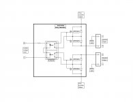
Those aren't steering diodes, in fact, if everything is working right, they do nothing at all. They're there to protect the MOSFET's in the unlikely event there's a large inductive kick-back at power down. When the MOSFET's are on, thier Rds (drain to source resistance) is a small fraction of an ohm, the diodes are shorted out and don't conduct. when MOSFET's are off, diodes are back to back and also will not conduct. The cricuit works fine without the diodes in there at all, I just felt it would be prudent design practice to put them in. And the device you call a photo detector is a photovoltaic MOSFET driver, when a driving current lights the internal LED's they shine on photo diodes which generate a low current voltage beetween 5 and 8 volts, enough to turn on the MOSFET's.
Here's how the circuit works. When power is applied to control voltage input, current of about 5ma (as determined by input voltage, minus total LED voltage drop, through current limit resistor) turns on LED's. Output voltage is then applied to MOSFET gates and switches them on. The advantages of using this circuit verses a mechanical relay are; faster on-off switching, no mechanical contacts that can arc and burn (or weld themselves together!), can be driven by a wide range of voltages with small current requirement, is easily scaled for higher power amps by parelleing MOSFET's if need be, and they work quietly - no mechanical noise when turned on and off. Only possible disadvantage is the small Rds could very slightly decrease damping factor at amplifier output, and the MOSFET's Rds will vary a tiny bit depending on currennt level though them, but after extensive listening tests I've never heard any audible artifacts of any kind. With all the advantages, I'll probably never use a mechanical relay for speaker switching agian.
Mike
Bonsai - build two SMPS power MOSFETs based relay.
Sorry, I am not disclosing more.
Yes Pavel, I can also thimk of a way to do this. Maybe I will try it. Sorry, that's all I will disclose!
This should work, similar principle with auxiliary contacts is used in HV power circuit breakers.
There is still a question of capability of Amplimo relay to break DC arc.
Yes this is the issue. When you apply 75 volts across 6 ohms you have about 12A. The relay has to handle that.
- Home
- Amplifiers
- Solid State
- Output Relays