What needs to be done which will make the EF devices unconditionally stable withOut additional Ls in series with the speaker cable/spkr? Greater phase margin or ??
Yes, only more phase margin than most amps now have would make them unconditionally stable.
Dyna's tube amps in the fifties had such stability, but the more recent ss designs are challenged in this respect.
What's the actual benefit of that C4..? Stability purposes or does it improve THD, slewrate? To me its effect seems to stabilize a (too) fast input stage.
In July 1970 WW, JLLH wrote in his article "15-20W Class AB Audio Amplifier" about this form of compensation: (The Class-A Amplifier Site - JLH Class-AB Amplifier)
"The 390pF capacitor between the emitter of Tr1 and the collector of Tr2, and the 8.2ohm resistor in series with the 0.1uF capacitor across the output, provide the necessary phase-angle correction and define the high-frequency gain of the feedback loop. With the values shown there is a 6 dB/octave roll off beyond 100kHz, and the system is completely stable under all load conditions. However, with the use of a large value capacitive load there will be some overshoot on a rapid transient. The author believes that it is desirable for tonal purity, for such overshoots to be eliminated, and it is recommended, therefore, that the 390pF capacitor be shunted with a 680pF 1.5kohm combination where it is intended to drive electrostatic speaker systems. However, on normal loads this merely reduces the h.f. roll-off point, and the power output available in the 30-50kHz region, and can well be omitted."
And the A40 in 1978, and the A20 {shown below} from the DIY article in Audio magazine, Feb. 1977 (link; be sure to download the pdf) Unlike the A40, the A20 doesn't even use a push pull output stage.
Take it up with the 1978 version of Nelson Pass; he's the one who designed the A40 and referred to its capacitor C4 as "lead compensation". (link 2)
_
Thanks for pointing this out, Mark.
The very short loop formed by the capacitor around just 2 transistors probably is why no further compensation of that compensation loop is necessary.
Notwithstanding Nelson, I would still not call it a lead capacitor. From the point of view of the feedback resistor, it is looking into a Miller integrator. But, each to his own semantics.
Cheers,
Bob
That's like saying you cross the street often and have yet to be run over by a car, in all honesty it is a rather poorly argumented reply.
I agree. If you are just designing an amplifier for yourself around your home, and not for widespread use with who-knows-what load, you will usually be OK without the inductor. But, in general, you really have to do your homework in lots of testing if you want low risk of instability under all conditions.
Cheers,
Bob
Even with the MIC as shown in the A40' a 100 nF capacitive load really causes the response to kink significantly, and the PM to degrade.
I just think, to your point Bob, that relying on the cable L to isolate the capacitive load is not good practice unless you have complete control over the values involved - which typically you would not.
I might be able to post some sims up tomorrow that illustrate the point.
I just think, to your point Bob, that relying on the cable L to isolate the capacitive load is not good practice unless you have complete control over the values involved - which typically you would not.
I might be able to post some sims up tomorrow that illustrate the point.
What, if any, would be the 'con' or negative affect of doing so?
THx-RNMarsh
The negative affect of having high PM is that the amp may not be performing optimally. The old stability vs performance trade off.
Which may be an argument for including the inductor?
Nigel, for most amplifiers, an output inductor is recommended. For many decades, 2uH was the usual value. I have found 2uH to be audible, I have no real opinion about 1uH or less, but it should be OK, IF it is necessary to use it. To test an amplifier for stability, you have to load it with a variety of cap values, with a square wave at low levels passing through the amp. You will generally find ONE value of cap that could put the amp into oscillation. My experience is that cap values around 0.1uf can be a BIG problem. Faster amps need a smaller value to oscillate.
Charles Hansen, Nelson Pass and I have elected to NOT use an output inductor, because we found that the amps sounded better. However, just throwing together an amp without extensive worst case testing is not recommended.
Hi John,
These are good points. However, small-signal testing for stability with a square wave is insufficient, as many of the parameters in a output stage change with voltage and current conditions. Most of us have seen how a marginally stable amplifier will break into an oscillation burst somewhere along a high-level sinewave, often just after the peak, even with a resistive load.
One of the tests mentioned earlier in the thread was to have a small-signal HF square wave riding on a large-signal sinewave to assess stability over a range of conditions, and I like that idea. To make the results easier to see, one could probably cancel out most of the LF sinewave by taking the LF generator signal and subtracting it from a properly-scaled version of the amplifier output. This would leave just the square wave to look at. One could also use an HPF to attenuate the LF sinewave as long as it did not mess up the HF square wave too much. Of course, one could do both in combination: cancel the LF as best you can and then HPF a little bit to further attenuate what remains of the LF signal.
Cheers,
Bob
How to do it properly according to Halcro
Hi Bonsai,
That Halcro inductor doesn't look like many uH, but I was never good at eye-balling inductance. What do you think? Might it be 1uH?
Cheers,
Bob
Hi Bonsai,
That Halcro inductor doesn't look like many uH, but I was never good at eye-balling inductance. What do you think? Might it be 1uH?
Cheers,
Bob
I can't tell from the image which measures about 10x15pixels

How much phase margin would make the amps unconditionally stable? Approximation generally... in sim.
What, if any, would be the 'con' or negative affect of doing so?
THx-RNMarsh
Hi Richard,
In regard to capacitive loading without a series inductor, I worry not only about the phase and gain margin of the global loop, but also the possibility of local HF output stage oscillations. Emitter followers can be de-stabilized by capacitive loads. Moreover, such local instability in an output stage can be a very strong function of layout. I tend to be a bit paranoid about local instabilities sometimes, I admit.
BTW, I also worry about speaker cables acting as transmission lines at high frequencies (of course, not at audio) where they may be able to present nasty impedances to the amplifier in a frequency range at or above the unity gain frequency. It is important that we cannot always view a speaker cable as a simple lumped model of a transmission line.
It might be interesting to test an amplifier with various capacitive loads placed at the end of a 20-foot speaker cable.
Cheers,
Bob
One other approach, rather than relying on output Zobel and Thiele networks is to create a pick-off point for an additional feedback loop before the emitter resistors by using small value Cs. We've done this on the ExtremA design (see below), you'll notice these signals get fed directly to the LTP at the input.
An externally hosted image should be here but it was not working when we last tested it.
This looks a little dangerous to me, as the signals at the top and bottom output transistors are highly nonlinear outside of the small output stage class A range. The capacitors are then being called upon to perfectly sum these two signals. I'm guessing the tolerances of the small capacitors and the emitter resistors would spoil an accurate summation. An imperfect summation will create distortion by feeding back a slightly distorted signal.
Cheers,
Bob
I respectfully beg to differ Bob
Shown below is the residual THD at 40W/1kHz. The 2nd harmonic is due to the fact we have not used Hfe matched transistors throughout. What can be read from this figure is that at 40W the true THD is 0.00008% (-122dB). A figure you will be hard pressed to find with any commercial amplifier. The nature of class-A distortion and its harmonic distribution allows us to extrapolate down to lower signal levels. At 1W the distortion would be around 0.000002% (-154dB) something which can’t be measured directly.
An externally hosted image should be here but it was not working when we last tested it.
This looks a little dangerous to me, as the signals at the top and bottom output transistors are highly nonlinear outside of the small output stage class A range <snip>
@Bob,
My apologies, I forgot to mention that the OPS is a class-A self-bias design, hence it always runs in class-A (100W/8R as shown in the schematic). Only when pushed hard (>rated class-A output power) it enters class-B territory by means of a different mechanism that modulates the OPS input transistors. The THD hits a proverbial brick wall at that point.
Sander,
your circuit (the front-end) has two major issues:
1) horrible step response, this is mostly affected by R31 + C4, 10R + 1nF PRE load. Attempts to lower C4 finished with local oscillations. I believe you do not want for me to show the step response.
2) large thermal drift of output offset voltage. It is acceptable only in case that input is coupled through capacitors. And it is not easy due to 2k2 input impedance. 10uF polypropylene to be used.
More humbleness would help.
Last edited:
Sander,
your circuit (the front-end) has two major issues:
1) horrible step response, this is mostly affected by R31 + C4, 10R + 1nF PRE load. Attempts to lower C4 finished with local oscillations. I believe you do not want for me to show the step response.
2) large thermal drift of output offset voltage. It is acceptable only in case that input is coupled through capacitors. And it is not easy due to 2k2 input impedance. 10uF polypropylene to be used.
More humbleness would help.
@Pavel,
1) We already discussed this, this is fixed by a simple component value rescaling and I am a bit puzzled as to why this hasn't shown up in our measurements. Bruno has measured the prototypes and final design front to back several times, I'm sure he knows what he's doing. But I can certainly ask him to see what he thinks?
2) Not seen issues of that nature before. Take notice that the DC offset trimmer needs to be set after the temperature of the OPS has somewhat stabilized. Also, all output transistors need to be on the same heatsink, do not make the mistake of using two separate heatsinks for each half of the bridged OPS as you *will* see a DC offset indeed.
As for humbleness, I'm not stepping on any toes am I? I'm merely suggesting the approach we used on the ExtremA, Bruno was pretty keen on using this approach rather than the conventional Zobel/Thiele networks.
I have done a Spice simulation with a simple loudspeaker model and a transmission line (3m cable) with and without a Zobel inductor (2uH || 22 Ohm).
There is no difference in input impedance below 10 Mhz. The conclusion is:
If the amp is driving a cable and a loudspeaker, the Zobel inductor L4 can be omitted.
BUT there are people testing amps with capacitive loads. In this case the Zobel inductor helps to avoid local oscillations in the output emitter follower.
For 8 Ohm resistive loads the results are similar.
R-Udo
Attachments
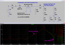
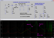
The next picture shows the influence of the R-C Zobel network.
Without the Zobel R-C the line input impedance is capacitive above 600 kHz.
This is critical, because in this region the current gain (beta) of the emitter follower output transistors is falling with 6 dB/octave.
A capacitive load is transformed to a negative resistance at the base. This can lead to oscillations. A R-C at the base, a base stopper, or a R-C at the output can help to stabilize the emitter follower.
A slow output transistor has a Ft of 5 Mhz and a Beta0 of 25. Beta is falling
above 5 Mhz / 25 = 200 kHz and is 1 at 5 Mhz. In this region transistor current
gain beta is Beta0/(j*2*pi*f).
The Zobel R-C is resistive at this frequencies and dampens oscillations.
It is remarkable that this has nothing to do with global feedback stability.
R-Udo
Attachments
- Status
- This old topic is closed. If you want to reopen this topic, contact a moderator using the "Report Post" button.
- Home
- Amplifiers
- Solid State
- Output inductor in power amps - pro and con