I happen to think your explanation is all wet, at least with respect to Nelson Pass's A40 class A amplifier. It has no output inductor. Making cheap-and-cheerful substitutions for the long-obsolete Lambda power darlington output devices, simulation of the A40 schematic in the above link says the gains areIn Nelson's case his amplifiers (not familiar with A40 circuit details - is it ZGF?) they tend to be low feedback types, so the HF poles fall close to or below the 0 dB gain point. This type of amp can tolerate nasty loads without an output inductor much better than high loop gain types.
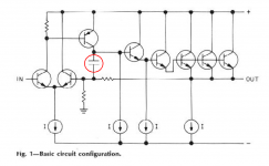
- First stage (NPN diffamp with resistor load): +11 dB
- Second stage (PNP common emitter with current source load): +68 dB
- Output stage (darlington EF push-pull biased @ 1.5 amps): -0.2 dB
- Entire amplifier: +79 dB
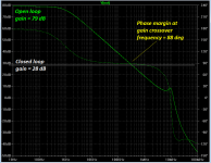
The simulated open loop frequency response is attached. Closed loop gain is (1+(R5/(R4+R3)) = 24.3X = 28 dB, which I have overlaid on the simulator results as a thin white line.
If you decide to simulate the A40 yourself, I think you will enjoy fiddling with the compensation capacitor C4; Pass has connected it in exactly the configuration that Douglas Self warns against (APAD 5th ed. Fig 8.2), from 2nd stage collector to 1st stage base. Pass calls this "lead compensation" (Fig. 7) and shows that it improves damping factor compared to the "lag compensation" (base to emitter of 2nd stage) that Self favors. Your own simulator fiddling will also reveal the benefit or detriment the lead compensation has upon phase margin.
Possibly of note is Pass's remark that "Fig 7 also shows the high (300X), wide-band damping factor, which serves particularly well into low impedance, especially reactive loads." Perhaps this may be indicative of why he's comfortable omitting an output inductor.
Attachments
Last edited:
Clearly you did not read my commentary carefully, and have glossed over the facts.
As I noted in my post, I am not familiar with the A40 circuit details.
However, gain and phase margin have to meet certain minimum criteria if oscillation is to be avoided - no matter whose design we are talking about.
If NP s happy with the A40 performance into a capacitive load, who am I to argue?
I design for 60 deg phase margin (usually) and then add a 1 uH L to get to unconditional stability.
I am South African. So the 'wet' bit is lost on me bud.
I happen to think your explanation is all wet, at least with respect to Nelson Pass's A40 class A amplifier. It has no output inductor. Making cheap-and-cheerful substitutions for the long-obsolete Lambda power darlington output devices, simulation of the A40 schematic in the above link says the gains are
That doesn't look like a "low feedback type" to me.
- First stage (NPN diffamp with resistor load): +11 dB
- Second stage (PNP common emitter with current source load): +68 dB
- Output stage (darlington EF push-pull biased @ 1.5 amps): -0.2 dB
- Entire amplifier: +79 dB
The simulated open loop frequency response is attached. Closed loop gain is (1+(R5/(R4+R3)) = 24.3X = 28 dB, which I have overlaid on the simulator results as a thin white line.
If you decide to simulate the A40 yourself, I think you will enjoy fiddling with the compensation capacitor C4; Pass has connected it in exactly the configuration that Douglas Self warns against (APAD 5th ed. Fig 8.2), from 2nd stage collector to 1st stage base. Pass calls this "lead compensation" (Fig. 7) and shows that it improves damping factor compared to the "lag compensation" (base to emitter of 2nd stage) that Self favors. Your own simulator fiddling will also reveal the benefit or detriment the lead compensation has upon phase margin.
Possibly of note is Pass's remark that "Fig 7 also shows the high (300X), wide-band damping factor, which serves particularly well into low impedance, especially reactive loads." Perhaps this may be indicative of why he's comfortable omitting an output inductor.
The compensation Self was referring to in his Figure 8.2 is Miller Input Compensation, which I described and used in my MOSFET EC amplifier in 1983. Self referred to its use by J. Linsely-Hood in 1989 and Marshall Leach in 1988. Self apparently did not realize that the loop so formed usually needs to be compensated itself for stability, albeit at a fairly high unity gain frequency above 10MHz. This form of compensation permits enormous slew rate to be achieved. My 50-watt MOSFET amplifier had a slew rate of over 300V/us.
MIC is neither lead compensation nor feedforward.
Cheers,
Bob
And the A40 in 1978, and the A20 {shown below} from the DIY article in Audio magazine, Feb. 1977 (link; be sure to download the pdf) Unlike the A40, the A20 doesn't even use a push pull output stage.Self referred to its use by J. Linsely-Hood in 1989 and Marshall Leach in 1988.
Take it up with the 1978 version of Nelson Pass; he's the one who designed the A40 and referred to its capacitor C4 as "lead compensation". (link 2)MIC is neither lead compensation nor feedforward.
_
Attachments
It's difficult to see how any amplifier can remain stable once you start injecting RF into the antenna that is formed by the speaker cable unless adequate filtering is employed. I think talk of phase margins and capacitive loads is only half the story (albeit an important half). It would be interesting to know how omitting the output choke affects EMC performance, both for regulations governing CE or UL compliance and on performance (e.g. distortion) measurements.
There are probably marginal cases too where a design appears stable, but a quirk of layout and a bit of RF will push it over the edge.
Brian
There are probably marginal cases too where a design appears stable, but a quirk of layout and a bit of RF will push it over the edge.
Brian
I have designed numerous amplifiers of all classes and never used an inductor on the output. I haven't seen this cause any problems.
That's like saying you cross the street often and have yet to be run over by a car, in all honesty it is a rather poorly argumented reply.
That's like saying you cross the street often and have yet to be run over by a car, in all honesty it is a rather poorly argumented reply.
No problems show up on the scope or in use.
Perhaps my designs are solid/stable enough that they don't need an inductor ?
Nigel, for most amplifiers, an output inductor is recommended. For many decades, 2uH was the usual value. I have found 2uH to be audible, I have no real opinion about 1uH or less, but it should be OK, IF it is necessary to use it. To test an amplifier for stability, you have to load it with a variety of cap values, with a square wave at low levels passing through the amp. You will generally find ONE value of cap that could put the amp into oscillation. My experience is that cap values around 0.1uf can be a BIG problem. Faster amps need a smaller value to oscillate.
Charles Hansen, Nelson Pass and I have elected to NOT use an output inductor, because we found that the amps sounded better. However, just throwing together an amp without extensive worst case testing is not recommended.
Charles Hansen, Nelson Pass and I have elected to NOT use an output inductor, because we found that the amps sounded better. However, just throwing together an amp without extensive worst case testing is not recommended.
No problems show up on the scope or in use.
Perhaps my designs are solid/stable enough that they don't need an inductor ?
You're missing the point entirely, please take a moment to read through the whole discussion.
It looks to me like you've plotted open loop gain [ed. in post #81] above, and not loop gain.
That's the open loop gain of the amplifier itself, without the feedback network; I plotted it that way to show that in fact the A40 has quite a lot of gain: nearly 80 dB at frequencies below the dominant pole. (Some readers couldn't be bothered to glance at the schematic linked in post #66, to see the high gain 2nd stage with current source load.)
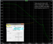
Please feel free to build a simulation of the A40 amplifier yourself, if you wish. This will allow you to simulate it including the feedback network if that's what you prefer. You may enjoy working out a way to include the positive feedback of the input bootstrapping network, in simulation. (I enjoyed that). I predict that your simulation results, plotting around-the-entire-NFB-loop-including-gain-resistors frequency response, will resemble the figure below. Notice that the phase margin is 88 degrees, the same number as in the post#81 image.
_
Attachments
So, someone tell me again, what does the 1uH do that the larger Ls of the speaker cable does not do?
It's supposed to guarantee that no external load, either the speaker or the wire, can cause instability.
Some speaker cables have significant capacitance, for example.
Last edited:
Please feel free to build a simulation of the A40 amplifier yourself, if it's important to you. If it's not important to you, if you can't be bothered, then ... don't bother.Please load the amplifier output with 2 Ohms and 2 uF in // and let's see the plot.
I think the second pole will move up in magnitude and the PM will degrade.
Just think, if your hypothesis is correct, you'll be able to tell Nelson Pass that you've found a weakness in one of his designs. Fame and glory await. If it's important to you.
The A40 is a public-domain laboratory for experimentation with an output-inductor-less amplifier. Either in simulation, or hardware, or both. Have some fun with it.
Last edited:
It's supposed to guarantee that no external load, either the speaker or the wire, can cause instability.
Some speaker cables have significant capacitance.
For awhile here i thought it was just about making things work well only for bench testing 'cause the Ls of any speaker cable is >1uH. [But that speaker cross-over is something else].
What needs to be done which will make the EF devices unconditionally stable withOut additional Ls in series with the speaker cable/spkr? Greater phase margin or ??
THx-RNMarsh
Last edited:
Please feel free to build a simulation of the A40 amplifier yourself, if it's important to you. If it's not important to you, if you can't be bothered, then ... don't bother.
Just think, if your hypothesis is correct, you'll be able to tell Nelson Pass that you've found a weakness in one of his designs. Fame and glory await. If it's important to you.
The A40 is a public-domain laboratory for experimentation with an output-inductor-less amplifier. Either in simulation, or hardware, or both. Have some fun with it.
You seem to be the one that is questioning the use, or not, of an output L.
The plot you have shown is into an 8 ohm load. If you load that sim with a cap, you are likely to get stability issues - output L will go someway to preventing that.
Far be it for me to build a model of NP 's amp. I am quite comfortable with my approach and the reasons as to why the stability is affected.
So, someone tell me again, what does the 1uH do that the larger Ls of the speaker cable does not do?
THx-RNMarsh
LoL - the pro 'L' posse (me included!) used that same argument as to why adding a low value L was not going to affect audibility - speaker cable and speaker x-over L are far bigger.
But, if you want a bullet proof design, especially with the fast devices available today, the inductor does mean you can drive just about anything without problems. I think some designers rely just on the speaker cable L.
Besides all this technical discussion, big coils just look cool.

- Status
- This old topic is closed. If you want to reopen this topic, contact a moderator using the "Report Post" button.
- Home
- Amplifiers
- Solid State
- Output inductor in power amps - pro and con