Anybody using any kind of LS protection additionally ?
It may be worth looking at xrk971's latest protection boards, IIRC they're good for 150VDC and being Mosfet based should do a better job than a relay. I've not thought through their use beyond this so don't consider this a recommendation, just a possible option.
Thank you.
Anybody seen/tried this ?
Btw looking at this etsy board, it looks pretty clever. I already got into touch with SRR-s, all of the relays starting (and keeping) my trafos are SRR type. Easier to drive by a microcontroller and almost never wears out.
Anybody seen/tried this ?
Btw looking at this etsy board, it looks pretty clever. I already got into touch with SRR-s, all of the relays starting (and keeping) my trafos are SRR type. Easier to drive by a microcontroller and almost never wears out.
Last edited:
Gents, I'm in the final stage of sourcing parts, all big things are bought, only smaller ones are missing.
I decided to use the amp in 2 modes: mode1 with volume pot for both XLR and RCA inputs, mode2 direct input, no attenuation, pure amplifier mode.
In the latter case, changing volume would be handled by my DAC in PRE-mode (where output signal strength is modified, actually acting like a preamp).
I'm trying to sum up all the gains from our conversations, volume pot version:
- feedback previously discussed: in the original design it changes with volume pot setting, so I would move it from grid of V1a to grid of V1b and swap drive phase for the EF86 tubes.
- I intend to decrease RCA input sensitivity from 500mV to 2.145 Vrms if possible, to accomodate the source nowadays I use, a DAC. (Peaks at +/- 3V).
- I intend to add XLR with input sensitivity prepared for my next DAC (4Vrms, peaks at around +/- 5.65V).
Uh, I tried to remain structured but I might have missed it, sorry.
I decided to use the amp in 2 modes: mode1 with volume pot for both XLR and RCA inputs, mode2 direct input, no attenuation, pure amplifier mode.
In the latter case, changing volume would be handled by my DAC in PRE-mode (where output signal strength is modified, actually acting like a preamp).
I'm trying to sum up all the gains from our conversations, volume pot version:
- feedback previously discussed: in the original design it changes with volume pot setting, so I would move it from grid of V1a to grid of V1b and swap drive phase for the EF86 tubes.
- I intend to decrease RCA input sensitivity from 500mV to 2.145 Vrms if possible, to accomodate the source nowadays I use, a DAC. (Peaks at +/- 3V).
By this gain reduction on your own OTL, did you mean the voltage divider method, or the cathode resistor method mentioned by you in #433 ?@Koonw #441: Not that complex! All you need is adding 2 resistors, bypassed with a jumper to switch so you can revert to original. I posted because you ask for it as usual. Beside I did the same gain reduction in my own OTL amp so I am quite happy and confident to share it.
- I intend to add XLR with input sensitivity prepared for my next DAC (4Vrms, peaks at around +/- 5.65V).
2 questions for me here:
1. According to original article, I can arrive with XLR signals on both grids of V1 via C1 and C2. Did Tim meant this with no volume pot at all ? (Kind of 'PRE-IN' for XLR).
2. Can I use 1 'global' pot for both RCA and XLR inputs' volume setting ? (I assume yes).
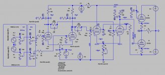
@Koonw #485: I posted this before, how to accept XLR input 4Vp, now again. gNFB is not connected to show how well the LTP balancing is, various level before feedback is applied. There appears to no mod is required except you make your own input pad at the XLR box or the OTL amp side. The only mod maybe the volume pot is dual gang 100k pot. The pot for XLR level adjustment is 600 ohms dual gang. If you adopt the way, move the feedback to the the other LTP input is meaningless.
Dual gang 100k - got it. But what do you mean with the 600Ohms dual gang ? (RV2 maybe, from 1000 to 600?) In any case, I assume I can leave feedback on the changed, new position at V1b, so it will serve better here in case of using RCA and means no change to the original setup when using XLR.
Uh, I tried to remain structured but I might have missed it, sorry.
I use voltage divider method before I discovered Cathode resistor method. The problem with voltage divider esp with 100k input impedance it's more susceptible to picking up hum required more screening. Cathode resistor method is fine but mine is not exactly TIM's but similar gain, and I have used it in 1st LTP. The 2nd stage is not a LTP, just common ground cathode. NFB is applied to right side of LTP. Changing the cathode resistor in each leg will reduce the gain and output z will drop. How much Gnfb is reapplied require you listening to speaker esp bass response.By this gain reduction on your own OTL, did you mean the voltage divider method, or the cathode resistor method mentioned by you in #433 ?
Volume pot can be only on left side only (as original), I think on the right side it can just omited connecting C2 directly to ground. The logic is that since Gnfb is applied to left side, both gain in this LTP stage will be identical, identical component need to be in place on the right side to ensure the frequency response is identical too. That is my logic for suggesting dual gang pot.1. According to original article, I can arrive with XLR signals on both grids of V1 via C1 and C2. Did Tim meant this with no volume pot at all ? (Kind of 'PRE-IN' for XLR).
If you use volume pot and XLR pot, of course you can leave feedback unchanged. Then the sensitivity would be doubled with XLR balanced input as both side are driven. In true differential balance stage equal Gnfb is applied to both side.In any case, I assume I can leave feedback on the changed, new position at V1b, so it will serve better here in case of using RCA and means no change to the original setup when using XLR.
Dual gang 1k pot is more common than 600 ohms https://www.ebay.com/sch/i.html?_fr...le-turn+carbon+film+potentiometer+1K&_sacat=0Dual gang 100k - got it. But what do you mean with the 600Ohms dual gang ? (RV2 maybe, from 1000 to 600?)
Last edited:
Thanks, this made a lot of things clear for me. For the dual gang pot: this is a 2nd pot I assume, with 1K. Where, for what purpose ? ") The sole purpose of that I can't see still and not because I understand electronics that good, but quite the opposite, still learning. So let's assume I have RCA and XLR inputs too, only using one kind of these at a time. Can the original pot (corrected according to the cathode resistor method) be used for both RCA and XLR ins, or do I need a 2nd pot for the XLR signals and exactly that's what you're talking about with the dual-gang 1K pot ? (dual: 1 part for normal and 1 for inverted signal).
The sole purpose of that I can't see still and not because I understand electronics that good, but quite the opposite, still learning. So let's assume I have RCA and XLR inputs too, only using one kind of these at a time. Can the original pot (corrected according to the cathode resistor method) be used for both RCA and XLR ins, or do I need a 2nd pot for the XLR signals and exactly that's what you're talking about with the dual-gang 1K pot ? (dual: 1 part for normal and 1 for inverted signal).
The sole purpose of that I can't see still and not because I understand electronics that good, but quite the opposite, still learning. So let's assume I have RCA and XLR inputs too, only using one kind of these at a time. Can the original pot (corrected according to the cathode resistor method) be used for both RCA and XLR ins, or do I need a 2nd pot for the XLR signals and exactly that's what you're talking about with the dual-gang 1K pot ? (dual: 1 part for normal and 1 for inverted signal).I have a lot of options for EF86-s, can you maybe recommend me some ?
Just read this article - might be close to reality ?
Following types are within my reach (distance, money, availability):
And btw, what's the typical rated service hours for a EF86 ? For the 6C33C-B I found such data, also for the 6N2P-ER-s, but for the EF86 some sites mention 10k hours, others nothing at all .. 5k as a baseline maybe ?
Just read this article - might be close to reality ?
Following types are within my reach (distance, money, availability):
- TAD
- JJ
- Telefunken (NOS)
- Tung-Sol
- Svetlana (NOS) Winged C
- Some other NOS types if I'm clever on eBay..
And btw, what's the typical rated service hours for a EF86 ? For the 6C33C-B I found such data, also for the 6N2P-ER-s, but for the EF86 some sites mention 10k hours, others nothing at all .. 5k as a baseline maybe ?
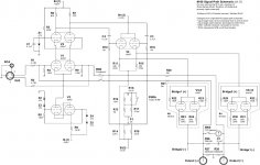
I presume your XLR preamp output Z is 600 ohms (transformer output) like AudioNote M10, so the output is best terminated into 600 Ohms resistor or pot otherwise terminated into 100k resistor or pot, in this case you can share the 100k pot since 600 ohms z can drive 100k z easily. See M60 attached. XLR input needs to be disconnected to prevent shunt of RCA signal if it is in use.Can the original pot (corrected according to the cathode resistor method) be used for both RCA and XLR ins, or do I need a 2nd pot for the XLR signals and exactly that's what you're talking about with the dual-gang 1K pot ? (dual: 1 part for normal and 1 for inverted signal).
Attachments
A Happy New Year to everybody! Vortex - my question is - why you need symmetrical input?
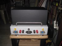
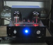
Hi Mr.Tecson! Could you share any visual of your setup?i am using a 90db floorstander for my Tim Mellows OTL...
i added an output dc blocking capacitor as a safety measure....
Hi Mr.Tecson! Could you share any visual of your setup?
Attachments
Hi VF, thanks, I wish you a happy new year too !A Happy New Year to everybody! Vortex - my question is - why you need symmetrical input?
I don't need balanced at all. I just stick to it for the sake of healthy amount of experimenting and also learning, during this amp-building journey of mine. It complicates things a little bit, I know, but the knowledge, tips&tricks, hints here and there.. they are golden for my better understanding where electricity goes.
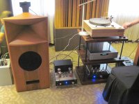
Beautiful setup and that concrete-looking chopped-top sphere-amplifier something is soooo f* cooolVery nice looking! Also very interesting rear wall construction! Any damping material inside? I have also a little problem with standing waves but like it is a temporal listening room I can´t build any massive solution here...
View attachment 1011678
)) Very well done. I wish I had such a room and playground, but my house building project is stuck at the very beginning (buying the appropriate plot for the house - the chosen one won't be sold yet). Earliest 2023 when I'll have a somewhat proper room hi-fi again.A practical question to my beloved OTL amp: according to original article, RV2 is close to the input tubes (DC bias). I can place the pot there somewhere near the input tubes.
How about RV3 ? Do the wires' length matter or not ? (So I can bring the pot to the side of the amplifier, with somewhat longer wires). If length matters and RV3 is picky regarding placement, I'll place it close to the pentodes then.
How about RV3 ? Do the wires' length matter or not ? (So I can bring the pot to the side of the amplifier, with somewhat longer wires). If length matters and RV3 is picky regarding placement, I'll place it close to the pentodes then.
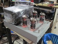
Hi Vortex! Added a bit better pic with elements mounted. RV2 as close as possible to V1. R7 is mounted directly in between of moving contacts RV2 and RV3 so therefore is good to keep the distance not so long. Wiring the RV3 should not be too critical like this is the DC path as much as I understand. But keeping the distances short is good in any cases. Try to seat both pots on top panel, it`s much more comfortable to control and adjust. Just the recommendation...A practical question to my beloved OTL amp: according to original article, RV2 is close to the input tubes (DC bias). I can place the pot there somewhere near the input tubes.
How about RV3 ? Do the wires' length matter or not ? (So I can bring the pot to the side of the amplifier, with somewhat longer wires). If length matters and RV3 is picky regarding placement, I'll place it close to the pentodes then.
Ah, and I was worried my amp wil be crowded. Joke aside, nice view and I like the extra insulation on some wires.
Thank you for the detailed photo and the comment, very valuable to me and correlates to what I was thinking as well. Now confirmed.
Huh. RV2 pot at input, right beneath the input tubes - no problem.
With RV3 I start to think now I'll have a sleepless night.
Amplifier chassis was brought today to the CNC shop for cutting holes and engraving. I'll email them today late evening or latest by tomorrow morning the SVG vector graphics files.
I think I don't mark the cutout for the 4x 4mm holes, I'll bore the holes to the trimpots depending on final location. This is the toughest part (I've never ever thought).
Joke aside, nice view and I like the extra insulation on some wires.Thank you for the detailed photo and the comment, very valuable to me and correlates to what I was thinking as well. Now confirmed.
Huh. RV2 pot at input, right beneath the input tubes - no problem.
With RV3 I start to think now I'll have a sleepless night.
Amplifier chassis was brought today to the CNC shop for cutting holes and engraving. I'll email them today late evening or latest by tomorrow morning the SVG vector graphics files.
I think I don't mark the cutout for the 4x 4mm holes, I'll bore the holes to the trimpots depending on final location. This is the toughest part (I've never ever thought).
- Home
- Amplifiers
- Tubes / Valves
- OTL designed by Tim Mellow with 4 6C33C?