@Koonw, I had a talk here locally with someone who tends to understand all that much better than I do.. he told me your idea is a great trick. On the original schematics, besides putting feedback onto the other triode, the only thing is to switch phase before EF86-s by connecting V2 grid to C3 and V3 grid to C4.
And apparently, that's it. Wasn't it trivial at first for the author ? (Or do we miss something ?) This way we can achieve constant feedback throughout power levels regardless of pot setting if I get it right.
If you do this you have to be aware that it also changes the way the output tubes work.
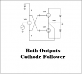
This is essentially a Futterman architecture.
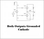
Futterman in his patent claim for his H1 OTL he erroneously stated that both output tubes worked in cathode follower mode; this was not the case because the way he hooked them up they actually were both grounded cathode.
Later designers of OTL circuits fixed that by swapping drive signals, requiring another stage front up.
See the attached pictures. 6C33C OTL
If you swap drive signals in Tim's amp you will turn cathode follower operation into grounded cathode operation.
Whether this makes any audible difference has to be investigated, so you can try it out. The amount of FB in this amp may make up for the change in output impedance which is a small signal issue anyway.
Attachments
Oh no.
Apart from phase inversion, tell me what else has changed? Play with sim if in doubt.
Apart from phase inversion, tell me what else has changed? Play with sim if in doubt.
Attachments
Last edited:
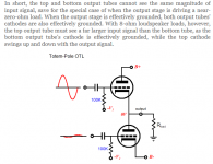
What I have learned is that in a totem pole architecture the lower tube works as grounded cathode, while the upper tube works as cathode follower which requires more drive voltage than the CF. Otherwise the output stage is grossly unbalanced.
OTL Amplifier Remake
I also learned that Futterman's idea was to bootstrap the splitter / driver such that the drive signal to one of the tubes is increased (or lowered) such that both tubes work the same and balanced.
I assumed that the Tim Mellow's also has balanced drive ... but you may be right because everything looks symmetric ...
Now this brings up the question: does this amplifier have an unbalanced output stage in the first place ? Or what circuit detail balances the drive then ?
And if it is unbalanced, does it only rely on GnFB to make up for that ?
Attachments
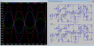
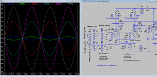
I posted this before, how to accept XLR input 4Vp, now again. gNFB is not connected to show how well the LTP balancing is, various level before feedback is applied. There appears to no mod is required except you make your own input pad at the XLR box or the OTL amp side. The only mod maybe the volume pot is dual gang 100k pot. The pot for XLR level adjustment is 600 ohms dual gang. If you adopt the way, move the feedback to the the other LTP input is meaningless.
Attachments
Last edited:
Sorento,
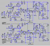
The key component that balanced the output is R13 100k resistor connected to output. This resistor is also plate load of ef86, this LTP will give a higher drive level to the top tube and lesser drive to the bottom tube thus balance is maintained. This makes top output a ground cathode amp (just like the bottom), with equal gain. There are more than one way to achieve balance drive.
PS, In more detail operation: The gain of LTP stage is determined by the input side tube, when the gain of other tube is reduced there is no effect on the gain of right side, so only the left side gain is reduced. Of course, Futterman OTL try to increase the gain of right only (bootstrap), but the left side gain will be increased also as described above and consequently output Z is higher and less accurate. But there another way that can increase the gain of right side and decrease gain of left: feedback is applied to tail of LTP!
Last edited:
Correction:
The key component that balanced the output is R13 100k resistor connected to output. This resistor is also plate load of ef86, this LTP will give a higher drive level to the top tube and lesser drive to the bottom tube thus balance is maintained. This makes top output a ground cathode amp (just like the bottom), with equal gain. There are more than one way to achieve balance drive.
PS, In more detail operation: The gain of LTP stage is determined by the input side tube, when the gain of other tube is reduced there is no effect on the gain of left side, so only the right side gain is reduced. Of course, Futterman OTL try to increase the gain of left only (bootstrap), but the right side gain will be increased also as described above and consequently output Z is higher and less accurate. But there another way that can increase the gain of left side and decrease gain of right: feedback is applied to tail of LTP!
The key component that balanced the output is R13 100k resistor connected to output. This resistor is also plate load of ef86, this LTP will give a higher drive level to the top tube and lesser drive to the bottom tube thus balance is maintained. This makes top output a ground cathode amp (just like the bottom), with equal gain. There are more than one way to achieve balance drive.
Ah, this is what I was looking for and what I failed to see.
That enlightens me, thank you very much.
Trafos arrived, progressing.. today I just made the little voltage stabilizer circuit for the microcontroller (feeding it from a 6.3V AC tap) - it works, no smoke yet. 
This thing is heavy now like a beast. The 4mm aluminum bottom can hold the weight seemingly good, without any sign of bending (I'm surprised) but for safety I think I'll bore a hole for a 5th foot into the middle to give some relief to the whole structure. Omg. This toy is definitely a proper tool for self defense too
Next I'll do monoblocks I swear.. lol.
Anyway, I'm more than excited now. Seeing where I can place the trafos and how much space I have left towards the back, can't wait to have the cnc and engraving work ready on the chassis and finally begin to mount the tube sockets onto the top plate.
Not sure if this is a common practice, but I decided to bury the input tubes (6N2P-EV) into the chassis in a horizontal position, with their sockets just above the RCA/XLR inputs.
For that I'm going to create a smallish stainless steel folded panel and mount the tubes onto that. This way I think I will have very short signal path, and some RF/EMI shielding for this most sensitive stage. Heating will be DC here using the 9V transformer taps + rectifier.. and probably AC using the 6.3V taps directly for the EF806S. And a separate trafo for the 4x 6S33S-V tubes' heating (12V AC).
The in-chassis 6N2P-s will have plenty of cutouts on end of the top panel right above them for good heat dissipation, air intake will happen through many small cutouts on the bottom panel, on the front side. So there will be a natural air circulation which I hope will be good enough to keep the amp within limits during the Summer season too.
The rest of the inside will be protected by an additional steel panel from the heat (generated by input tubes and the 6S33S sockets' heat).
That's it so far.
Gentlemen..
Can I avoid RV2 and RV3 with a simple "automation" ? (No microcontroller, just a simple circuit-based solution to null DC offset (RV2) and to keep bias at 200mA (RV3)).
Would it harm the design or not ? At the moment I don't see the advantage of setting these values manually (and periodically checking them), why not do this with some few additional components electronically ? (I think it's called 'servo' but I'm not sure).
Hi Vortex!
I believe here is no point to struggle with "automation". The amp is stable when you have found the good set of tubes and does´nt need any adjustment continuously. Thermal processes in 6C33 are slow but once warmed up they will stay stable. Over engineering is not always needed...
I believe here is no point to struggle with "automation". The amp is stable when you have found the good set of tubes and does´nt need any adjustment continuously. Thermal processes in 6C33 are slow but once warmed up they will stay stable. Over engineering is not always needed...
Hi Vintage Fart, thank you, this makes me sleep a bit better now.
Btw I still have one of your older comments from here, saved in a TXT file for the future when I begin to make this amp.. (now time has come, parts are arriving continuously). This nickname was somehow familiar to me. Cheers.
Btw I still have one of your older comments from here, saved in a TXT file for the future when I begin to make this amp.. (now time has come, parts are arriving continuously). This nickname was somehow familiar to me.
Cheers.
Last edited:
Btw how long shall I precondition the tubes ? I've heard of heating them for some hours, with cathodes, grid and anode connected to ground maybe ? To avoid some kind of contamination (?)..
I have a 5-7V (adj) SMPS, 200W, perfect for the story.
I assume this process applies not only to 6S33S-V but other tubes too, so in my case EF806S and 6N2P.
I have a 5-7V (adj) SMPS, 200W, perfect for the story.
I assume this process applies not only to 6S33S-V but other tubes too, so in my case EF806S and 6N2P.
one common 6,3V SMPS for pre stages heating.
One of your older comments to me..
How did you resolve the huge voltage difference between cathode and heaters in such a case, with a common SMPS ? As you see I have built toroidal trafos for linear PSU and I explicitly said the trafo makers there will be some 450-ish Voltage difference between secondaries to pay attention.. they increased insulation strength between each winding onto a 4kV limit. (Standard is maybe 1kV, I don't know).
why don't you just install the heater trafo, the tube sockets, wire up the heaters, just the heaters, nothing else, insert the tubes, turn it on and watch them glow for a while .... no need for smps nor HV nor grounding ...
The 6c33c pulls 3.5A @ 12v or 7A @ 6v when hot but 7...10 x that when cold. 70 A for a single tube will inevitably trigger the over current protection even that of a 1kw smps, let alone 4 of them.
Use your heater trafos and do them all at once...
The 6c33c pulls 3.5A @ 12v or 7A @ 6v when hot but 7...10 x that when cold. 70 A for a single tube will inevitably trigger the over current protection even that of a 1kw smps, let alone 4 of them.
Use your heater trafos and do them all at once...
Last edited:
Well, if I remember correctly I already put 2x 6S33S-V tubes onto my Meanwell 200W SMPS. Not a single issue, I heated them for some minutes. Of course all 4 would be too much.
Now all 4 are running since more than an hour from the toroidal trafo as intended, 12V AC. Plenty of heat above my head (on the top shelf of my computer desk).
How long (hours) do you recommend to heat them ?
Now all 4 are running since more than an hour from the toroidal trafo as intended, 12V AC. Plenty of heat above my head (on the top shelf of my computer desk).
How long (hours) do you recommend to heat them ?
Thanks.. Oh well, right. I'm heating with electric panels anyway (just moved in into my parents' weekend-house for couple of months 'til my new place is built and ready).
Now feeling this heat coming onto my forehead I think I can safely unplug the electric heater panel from the wall and I still won't freeze in the next hours
Now feeling this heat coming onto my forehead I think I can safely unplug the electric heater panel from the wall and I still won't freeze in the next hours
- Home
- Amplifiers
- Tubes / Valves
- OTL designed by Tim Mellow with 4 6C33C?