Well, I'd like to share some ac coupled amp stuff actually used for party amp and bass guitar amp.i've never heard that intro bass guitar sound, all the way up and down the scale, convincingly like a real live bass guitar, with any capacitively coupled amp)
No need to inconvenience a TL072.
")
http://www.diyaudio.com/forums/chip...e-no-lossy-emitter-resistors.html#post3491311 (post#29, and 28 too)
So, that's a start, but use an array--stack a Pair 470u, or Three 330u, or Four 220u on that thing. The 16v caps fit just fine. Caution, if there's not enough capacitance, the diodes will switch And conduct your bass signal as well as possible momentary bursts of DC. For test only purpose, a couple of bat86 (0.3v) or FR (0.5v) will provide solid proof by Not switching IF you get your in- coupler big enough.
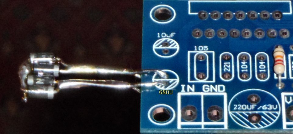
However, this 1.4v (photo) is better for ordinary use, so it doesn't switch by accident. (that piece does need caps added to it)
To go along with that, see also post 30; and, even though it looks like there's going to be less power that way, decoupling forced to work practically Increases of usable peak power. Really a lot.
If you had the following conditions: TDA7293 with enough gain to please it, in- coupler big enough, and decoupling forced to work (post#30) then you can increase the size of your input cap, up to 10uF.
That amp, with the mods, emits an epic bass dynamic punch (that does take a bit of gain too). Normal version is seeing some party, club, and pub use. Bridged version is seeing some service with bass applications and other concert duties. That includes bass guitar with fully ac coupled amp.
So, in some cases, you're hearing real live bass guitar through full ac coupling several times over.
The scribbling has worked.Daniel--I'm a little confused about your mute/stdby modification. (more just keeping track of where you're talking about)
Might you be able to point out (just scribble in MS paint or something over the standard schematic) what you're addressing?
Much obliged,
D
With the schematic attached, you can put a zener, a white led or an led string, in series with pin 10. That will cause the sequence suggested by the datasheet. It removes even the excuse for a mute cap. That is stylish, and unnecessary.
Actually, mute and standby have been working as shown by the schematic (attached) in many examples for several years, so the change suggested is not needed.
What is actually needed is minimizing the bulk of the mute and standby components and that is shown in the schematic attached. It is important that everything else be as close as possible to the chip. We would not want to block off space needed by either small signal resistors or important caps. So far, that has been unavoidable. Therefore I have minimized the component count for mute and standby.
The durability of that mute and standby arrangement (as shown in the schematic attached) has been proofed brutally for years and with multiple samples. It is less likely to cause breakage than the datasheet schematic. lolz! understatement.
I almost forgot to mention! Setting the gain divider resistors in the range of 32x~38x wouldn't possibly prevent you from adding supplementary negative feedback with comp and composite means. . . which would indeed lower the gain far more than the resistors could.
The schematic also shows "same||same" bypass technique, which is an uncomplicated way to block the need of audiophile caps, by simply using ordinary caps in a higher quality manner. That is a great time-saver.
The ultra low RC frequency of the in- coupler has also removed the need of a DC tracker.
The schematic has used the 6A05 as a no-sag resistive element in a crc type filter for reducing distortion (the other C, not shown, is your power supply reservoir); however, if that is too strong, then you can substitute MUR or MBR1645. High-current, Low-voltage is key at that locale so that the diode's datasheet forward voltage drop vs current graph looks as close as possible to a straight up wall, and therefore a no-sag crc. Reducing midrange distortion without reducing bass may seem like a contour, but I thought it fantastic. Also, that way the decoupling is forced to actually work, and when that is more stable, the gain can be set a little lower. So, those odd looking diodes are there on purpose.
I made this up to provide a really good head start.
Sorry about the rarer value 25k resistors--22k will not do.
Attachments
Last edited:
It is when you didn't make a composite amp that you might want to make parallel amplifiers so that some distortion ends up in output ballast resistors instead of speakers.Ultimately, I'm looking at a composite setup driving parallel chips and DC servo correction. Probably the LM49710 like everyone else and a TL072. (Why mess with success?!) Might try to bias the parallel chips against each other to pull them up (just a hair) and mitigate some of the crossover distortion. Will start with just the basic 7293 with point-to-point, though, and try to figure out how much lead/lag it needs to get the gain down closer to 12-15, then add the servo, then use the 49710 as a unity-gain buffer to drive the parallel chips (think this will be a much better overall solution than using the 7293's intrinsic paralleling, but that remains to be determined), then finally composite.
However,
When there's a composite build, Parallel amplifiers is similar to parallel darlingtons, which is similar to herding cats.
So, parallel outputs (TDA7293 datasheet, master/slave) would be much easier when the plan is making a composite amp. Composite amp will remove crossover distortion via feedback.
If you're going without tweeters and thus necessitate low power to avoid cone breakup, then what do you think of the very low gain LM675? http://www.ti.com/lit/ds/symlink/lm675.pdfThis will be to drive a 2.1 setup that reuses the subwoofer from said system and some "simple" corner horns driven by full rangers.
That's a cinch!: 5 pins easy layout, fair job with the decoupling, a simple supply and a 12+12 transformer. . . Presto!
Last edited:
Already own the parts and power supply, so I'm going with the lowest path of forward resistance by using what I have already.
All good ideas, nonetheless, and I appreciate the back and forth brainstorming. When I get a chance, I'll document my entire thought process in a proper thread.
My thinking on running the parallel 7293's through and through is that a 49710 will have little problem driving the respective parallel front-ends of those chips, and that means each output stage (after the link-in on pin 11) will have greater drive and allows the layout around each specific chip to be a bit tidier. Minus is the need for current-sharing resistors and individual servos. We'll see. That's a long ways down the line.
First order of operation will be a single chip compensated for lower than advertised gain with clean point-to-point layout, proper zobel/nortons, and good bypassing. Lots to learn!
All good ideas, nonetheless, and I appreciate the back and forth brainstorming.
When I get a chance, I'll document my entire thought process in a proper thread.My thinking on running the parallel 7293's through and through is that a 49710 will have little problem driving the respective parallel front-ends of those chips, and that means each output stage (after the link-in on pin 11) will have greater drive and allows the layout around each specific chip to be a bit tidier. Minus is the need for current-sharing resistors and individual servos. We'll see. That's a long ways down the line.
First order of operation will be a single chip compensated for lower than advertised gain with clean point-to-point layout, proper zobel/nortons, and good bypassing. Lots to learn!
Last edited:
$2 compact DC tracker/servo replacer (attached schema):
For parallel amplifiers (two active inputs, both voltage amplifiers active) see attachment that replaces Two DC tracker/servos.
Theory: The idea for parallel amplifiers is to share all of the caps (because 20% can't match), but share none of the resistors. In this scheme, the caps aren't and can't serve as ballast, so very large capacitance is needed; likewise it will sound exactly like a DC tracker/servo has been used. A single large cap won't do. The diodes are present to avoid launching the inverting input into orbit. Both amplifiers share this one array as their in- coupler cap, and thereby achieve a matched reference point.
This is more compact than two DC tracker/servos.
Perhaps it is more doable?
Notes:
* I have not tested this.
* FB-Shunt label refers to, the groundside leg of your gain divider.
* A 15 pin ST chip must meet these conditions: No NC! All 15 pins work!
* Ignore this schema if master/slave with only one voltage amp.
* Not for use with a stereo amp.
Attachments
Honestly, with the low impedance output of a op-amp running as a buffer in front of the 7293/4, it will have no problems driving two, independent circuits (that are tied together as closely as possible on their outputs). With independent servos, a la BPA200, I'm unconcerned.
Given the low cost of TL072's and a handful of passives, I'm okay DC-coupling.
Given the low cost of TL072's and a handful of passives, I'm okay DC-coupling.
An electrically unnecessary exercise in style was needed to suit a target market? If so, here is the more fanciful version of TL072 featuring nicer published specs: http://www.farnell.com/datasheets/1862385.pdf
For parallel amplifiers (two active inputs, both voltage amplifiers active) see attachment that replaces Two DC tracker/servos.
It eliminates mismatch of the caps, but it might make offset worse on amp with significant input current.
Yes, the tolerance is finite. I was hoping there wasn't a worse caveat and glad there wasn't. Thanks for checking it!!!It eliminates mismatch of the caps, but it might make offset worse on amp with significant input current.
Took the plunge...
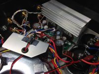
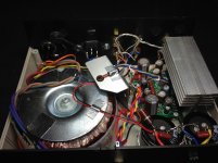
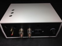
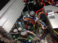
After having such good performance out another lesser TDA series amp, I just had to try the 7294. Bought two Chinese boards that include both channels in one PCB. After build and power on, I noticed that the polarity on the bootstrap capacitors is reversed both on schematic and PCB leading to wasting Elna Silmic IIs and time. All is well now. It is fed 37 VDC rails, uses a salvaged aluminum PC heat sink, 10K uF per rail, and is in a plastic case.
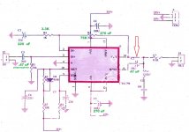
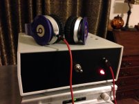
As can be seen in the schematic, green replacements to the supplied schema from China are noted and are from Daniel's audiometric suggestions providing 24X gain. Big thanks to him for his research and diligent work in tuning the circuit. I do not remember my Gainclone sounding this good. I added a headphone jack and confirmed with good headphones.
Ready for the next 7294 and though I have a second un-populated board, what is the 7294 board of choice? Even a dual chip mono would be of interest. I rather build with parts from Mouser and have two 7294 chips ready to go. This PCB is also too small to host the Elna 220/50 capacitors or the 22 uF for that matter.
Her are some pics and the schematic of the board I used.
Thanks.
After having such good performance out another lesser TDA series amp, I just had to try the 7294. Bought two Chinese boards that include both channels in one PCB. After build and power on, I noticed that the polarity on the bootstrap capacitors is reversed both on schematic and PCB leading to wasting Elna Silmic IIs and time. All is well now. It is fed 37 VDC rails, uses a salvaged aluminum PC heat sink, 10K uF per rail, and is in a plastic case.
As can be seen in the schematic, green replacements to the supplied schema from China are noted and are from Daniel's audiometric suggestions providing 24X gain. Big thanks to him for his research and diligent work in tuning the circuit. I do not remember my Gainclone sounding this good. I added a headphone jack and confirmed with good headphones.
Ready for the next 7294 and though I have a second un-populated board, what is the 7294 board of choice? Even a dual chip mono would be of interest. I rather build with parts from Mouser and have two 7294 chips ready to go. This PCB is also too small to host the Elna 220/50 capacitors or the 22 uF for that matter.
Her are some pics and the schematic of the board I used.
Thanks.
Attachments
Last edited:
As can be seen in the schematic, green replacements to the supplied schema from China are noted and are from Daniel's audiometric suggestions providing 24X gain. Big thanks to him for his research and diligent work in tuning the circuit. I do not remember my Gainclone sounding this good. I added a headphone jack and confirmed with good headphones.
curious about 3 things:
do i see altec or eminence sectoral horns in your pic?
which board did you use?
c3 is pretty small for a 22k input. are you ok with the bass you're getting? or perhaps you have a bi-amp topology?
btw i am also near DC (tysons actually)
Last edited:
curious about 3 things:
do i see altec or eminence sectoral horns in your pic?
which board did you use?
c3 is pretty small for a 22k input. are you ok with the bass you're getting? or perhaps you have a bi-amp topology?
btw i am also near DC (tysons actually)
Yes, you are correct, Altec 811 horns.
The bass is just right with my speakers, but I am always looking for more. Good point, that cap should not go any smaller than .47 uF with the 22K resistor which is forming a high pass filter starting at 15.4 Hz. They are currently Panasonic polypropylene.
You are just 13 miles or so east of me...
This is the board: Link
If anyone uses it, remember the bootstrap capacitors are incorrectly reversed polarity! wasted me a whole lot of time and some nice caps and had to rebuild a trace or two.
I think I will try some from Jimsaudio, I have gotten good stuff from this seller before.
Last edited:
This is the board: Link
If anyone uses it, remember the bootstrap capacitors are incorrectly reversed polarity! wasted me a whole lot of time and some nice caps and had to rebuild a trace or two.
the board has a big NFB loop area and a not so great bypassing setup, so i tend to think you will find a better board without much effort.
alternatively both daniel and i have had good results from point-to-point with all the key passives right at the 729x chip pins.
ps: i think i hear that altec horn begging for a tube amp :--))
Last edited:
the board has a big NFB loop area and a not so great bypassing setup, so i tend to think you will find a better board without much effort.
alternatively both daniel and i have had good results from point-to-point with all the key passives right at the 729x chip pins.
ps: i think i hear that altec horn begging for a tube amp :--))
OK, so I ordered these: link may try point-to-point if I get motivated enough.
...yes, there is a 300B tube amp laying around here somewhere. Right now the 7294 is working it magic, sounds really good.
OK, so I ordered these: link may try point-to-point if I get motivated enough.
...yes, there is a 300B tube amp laying around here somewhere. Right now the 7294 is working it magic, sounds really good.
interested to hear about the results once you have it fired up.
good luck!
for the p2p i found it helpful to create a single star ground point at the center of the chip face. i wire-wrapped together the dc 0-v and spkr 0-v lines then hung all passives' grounds off it. bent a few of the chip pins to have more working room and removed the nc pins as well.
worked for me YMMV. also did an LM3886 the same way.
Will do. Should I go with a 300VA or a 400VA toroidal? I am wondering if the 400VA is a waste.
Also will try a 1 uF input cap (with the 22K input resistor load) to see if I can squeeze any extra bass, though this first one is not shy at all on it.
Will do. Should I go with a 300VA or a 400VA toroidal? I am wondering if the 400VA is a waste.
Also will try a 1 uF input cap (with the 22K input resistor load) to see if I can squeeze any extra bass, though this first one is not shy at all on it.
as you probably know it depends on the load and how much the trafo sags and how much power you want to put into that load. but with a reasonably typical scenario i think 300VA is plenty for 2 of these chips.
daniel and andrew have written some useful posts with more detail on this subject.
- Status
- This old topic is closed. If you want to reopen this topic, contact a moderator using the "Report Post" button.
- Home
- Amplifiers
- Chip Amps
- Optimizing TDA7294 Output