You welcome. Thanks.
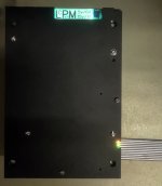
I was a little bit lucky to find/buy a flat cable which it fit to the task...
I will never understand how/why Oppo have found out that it should be used a whole bunch of 9 wires for the 5v hot line and only 4 wires for the ground for both 5v and 15v rails, on their connection cable... They thought that it may pass through more amps on the hot line than on the ground one...
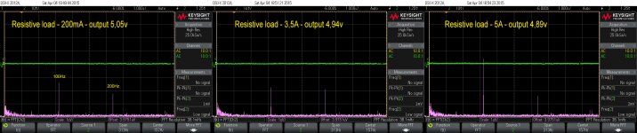
After first testing of my LPM into the player, I found out about some few imperfections, which it were corrected. Also I found a way to lower the noise/ripple level for the highest outputted current.
The resulted parameters of the LPM it surprised me enough. I could obtain just few µV ripple/noise for 5A out, on resistive load. Quite remarkable!
I have to mention that the transformer good parameters and quality it have a decisive role for the quality of the PSU.
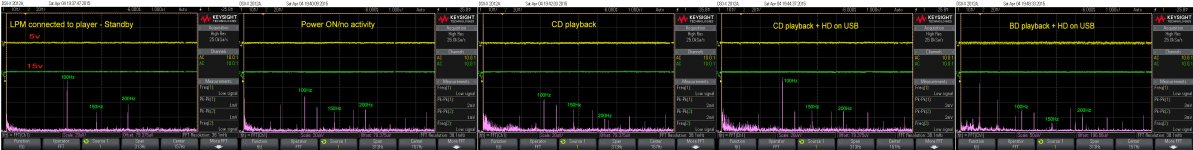
I have repeated the measurements with the last improved LPM, connected to the player. Here are the results.
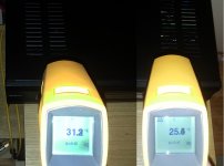
The temperature is almost the same. Around 42 dg. C in the mid area of the heat sink, for an average activity of the player (video/audio playback included CD). The dissipation increase to 48dg. C, when one HD is connected to the USB. However the ventilation inside the enclosure it do a very effective job.
The resulted parameters of the LPM it surprised me enough. I could obtain just few µV ripple/noise for 5A out, on resistive load. Quite remarkable!
I have to mention that the transformer good parameters and quality it have a decisive role for the quality of the PSU.
I have repeated the measurements with the last improved LPM, connected to the player. Here are the results.
The temperature is almost the same. Around 42 dg. C in the mid area of the heat sink, for an average activity of the player (video/audio playback included CD). The dissipation increase to 48dg. C, when one HD is connected to the USB. However the ventilation inside the enclosure it do a very effective job.
Attachments
Last edited:
Excellent work Coris! Now its time to enjoy the fruits of your hard earner labor.
1. Do you have the ability to measure THD+N, noisier floor and other spectral plots nothing that you have a beefed up power-supply from the RCA and XLR outputs?
2. What are the amplitudes of the power harmonics and the switching frequency of the digital power supply... (just curious)?
Good work indeed on squashing the ripple...
Excellent work Coris! Now its time to enjoy the fruits of your hard earner labor.
1. Do you have the ability to measure THD+N, noisier floor and other spectral plots nothing that you have a beefed up power-supply from the RCA and XLR outputs?
2. What are the amplitudes of the power harmonics and the switching frequency of the digital power supply... (just curious)?
Good work indeed on squashing the ripple...
Well, I may say that I do not have right now very much motivation to go deep in detailed measurements, because the differences in quality (before/after) are more than obvious. The improvements are important for both sound and picture.
I took some plots for the frequencies illustrated here, as i had available these digital files to run it on the player. Please note that these measurements here are taken on an extended improved device. The last improvement was this my LPM. So, the 100Khz spectre for these signals it shows like this.
For plots about SMPS, please see these posts (1026, 1254, 1262) where you may find lot of measurements done on SMPS rails (also with improved filtering), in both cases: with resistive load, as installed into the player.
Attachments
Last edited:
I have to mention something about the temperature inside the enclosure, while using this LPM.
The temperature last pictured, it was measured without the multichannel board mounted in place. With this board inside, the temperature increase with approx 7 dg.C. The multichannel board it increase the dissipation on the original analogue PSU regulators, and it obstruct a part of the airflow generated by the fan under it.
Definitely, the use of a serial PSU for this player it must be accompanied by a forced ventilation. The completely inaudible fan it do in this case a very good en effective job.
I have been following this thread, admiring the modifications of what people have done with their BDP-105, especially reading Coris' and Joe Rasmussens work. I plan to have my Oppo sometime soon.
Falling back to the discussion regarding SMPS vs. the traditional linear power supply -
I understand that the limitation of using a linear power supply inside the Oppo is that it has a higher heat output than the SMPS, so most are hesitant on replacing it for the SMPS.
Besides of cost, would it be feasible to replace the internal SMPS with a linear power supply in its own vented chassis? This will eliminate the concern of one frying their beloved Oppo due to heat exhaustion. What additional parts would be needed going down this route? If there are any drawbacks replacing the SMPS with an LPS with vented enclosure, what would they be? As an audiophile (as we mostly are here), I would like to get the most out of what I can with my equipment, so I/we am/are willing to spend a bit more than the average audio listener.
Thanks everyone for your time.
Last edited:
dbx01 I think the whole issue about the internal ambient temp may be a bit overblown. With an LPM and no fan venting we are only talking 40-45 or so degrees Celsius. Its not ideal, but internal temps in a PC or laptop can be that all day long and last many many years.
The only fixed component that gets really hot in the Oppo, correct me if I'm wrong, is the mainboard processor. Perhaps a better heatsink could be found for it, or have a small fan direct on that heatsink.
The only fixed component that gets really hot in the Oppo, correct me if I'm wrong, is the mainboard processor. Perhaps a better heatsink could be found for it, or have a small fan direct on that heatsink.
I have been following this thread, admiring the modifications of what people have done with their BDP-105, especially reading Coris' and Joe Rasmussens work. I plan to have my Oppo sometime soon.
Falling back to the discussion regarding SMPS vs. the traditional linear power supply -
I understand that the limitation of using a linear power supply inside the Oppo is that it has a higher heat output than the SMPS, so most are hesitant on replacing it for the SMPS.
Besides of cost, would it be feasible to replace the internal SMPS with a linear power supply in its own vented chassis? This will eliminate the concern of one frying their beloved Oppo due to heat exhaustion. What additional parts would be needed going down this route? If there are any drawbacks replacing the SMPS with an LPS with vented enclosure, what would they be? As an audiophile (as we mostly are here), I would like to get the most out of what I can with my equipment, so I/we am/are willing to spend a bit more than the average audio listener.
Thanks everyone for your time.
One may not be so extreme in appreciations
. A serial PSU it not get that hot to fry inside an enclosure. One should only establish an enough simple, but efficient ventilation, to solve the problem. A serial PSU it dissipate, but this negative effect of it, it can be minimised. In addition, one can add a forced ventilation, and everything it become just fine.
A passive ventilation it can well solve the problem too. In the case of Oppo BDP models, there is not possible to apply a passive ventilation. For 105/105D models the enclosure is actually full. For 95 models is even worse, as the enclosure is smaller and the processor it dissipate even more than in the newest models.
However, for 105/105D models there is possible to add a fan, so to create an enough airflow to ensure a very good ventilation, keeping both the main processor and the LPM at a low enough temperature to guarantee the best functional environment.
Indeed, the processor is one of the main and enough high heat sources for Oppo last models. A bigger heatsink for processor it may solve in a part the heat problem, but not enough. An bigger processor heatsink it will dissipate the same energy, but it will allow the processor to have a lower working temperature. The efficient solution is to exhaust the heat which is dissipated inside the enclosure. A passive ventilation does not work at all in such enclosure. In addition to the processor heat dissipation it come also the heat from the main serial regulators for analogue stages (stereo and multichannel).
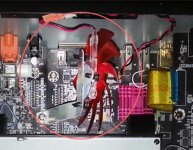
I have presented previously my solution: a fan placed inside the enclosure, not in contact with the exterior, which will only create an airflow in a wanted direction (the fan kit included with my LPM approach/kit).
The air input it will be the stereo board area (already provided perforations up and down), and the airflow output it will be the PSU area (upper left hand side). The stereo board area and the processor it will get so allways cool air from outside, and it will work actually at the room temperature. The airflow it will goes over the LPM heatsink and it will push the heat out through the left cover perforations (also some airflow guidances are needed inside).
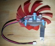
When the fan it not have direct contact with the external environment, the transmission of its audible noises, and vibrations is strongly minimised. Even more, the special construction of the fan system (see picture), as the very low power used to spin the fan, it damp/prevent completely any vibration to be transited to the rest of the mechanical system. The fan is completely inaudible from more than 10cm far from enclosure.
In my opinion, the heat problem introduced by a serial PSU use for Oppo players it is solved quite elegant and very efficient, by this ventilation approach.
I was a little bit sceptic myself when to use a serial PSU for the digital stage of the device, but I experienced the big improvements when using a such LPM. So I decided to proceed, design and realize this LPM.
Actually, I could not find yet a good explanation for the improvements when using a serial PSU for a digital noisy stage, but the improvements are real. So let`s use it so...
Attachments
Last edited:
By the way, to meet any eventual questions about when it may be available my LPM, I may say that this it will happen very soon.
Right now I do not have all the parts in my hands (ordered, on the way, etc). I still working to determine the best possible parameters for the transformer, while looking for the right provider for it.
Right now I do not have all the parts in my hands (ordered, on the way, etc). I still working to determine the best possible parameters for the transformer, while looking for the right provider for it.
Here is an idea for improvements (lowering the audible noise of the 95 fan):
http://www.diyaudio.com/forums/digi...ing-modding-new-oppos-bdp-93-bdp-95-a-20.html
USB port power is quite convenient to be used for a 12v fan...
http://www.diyaudio.com/forums/digi...ing-modding-new-oppos-bdp-93-bdp-95-a-20.html
USB port power is quite convenient to be used for a 12v fan...
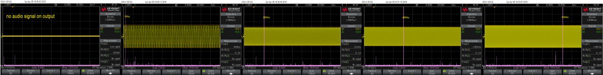
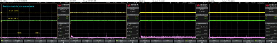
After optimizing the transformer`s parameters, I could obtain these measurements on my LPM.
There are three ways pictured here to measure the noise/ripple.
I chosen the "Averaging" which allowed me to go under 1mVpp on my scope. Also there is a larger spectre FFT which shows the obvious "silence" of this power supply. FFT shows RMS levels.
The temperature (both rails loaded for max current) do not exceed 45dg.C measured very close to the both regulators areas.
I may admit that the performances of this LPM are over my expectations. It measure too good to be used for a digital stage...
Attachments
My LPM is fully (power/rails) compatible with 95 model, but it may be some possible less compatibilities aspects: the LPM is a little bit higher than the original SMPS (no problem for 105 model), and the 95 model`s enclosure is a little bit lower. The 95 model it need more power on 5v (first generation processor), so the heat dissipation on LPM it may be a little bit higher than for 105 models (average load).
The biggest problem is the ventilation for a 95 model. The available space for an enough efficient airflow inside the enclosure is very limited. The huge board it full all the available space inside (components oriented downward).
However, there is possible to have a forced ventilation for 95 models too, but because of the very limited available volume inside the enclosure, the airflow is quite poor.
The 95 model is just at its limits when about the heat dissipation inside and a safe functioning. It can not work safe without forced cooling. Adding a new heat source from an LPM for digital stage, it may be a problem for a 95 model...
So far, i can see a solution to place the LPM outside the device, but this solution it may mean some modifications on the original chassis. The LPM it can be placed just under the player, or even better, beside it, on the right side of its enclosure, to minimize the cable length. A convenient hole have to be made on chassis bottom side, to get the connection cable inside, and into the main board. This it may not be very difficult operation. My LPM is designed to take in account and compensate the cable length power loss (active sense function). However, I appreciate that the already length of the flat cable it fit very well the distance from an (external placed LPM) to the main board connector (through bottom side of the chassis).
If placed outside the 95 chassis, the LPM itself do not need any special cooling, but the natural one. I think I have to provide an option for this LPM to be mounted into its own enclosure, when used as extertnal PSU. I will fix for sure this aspect, but this add on it will increase its price...
Another solution I can see so far in case of an old 95 model: buy a new one. Actually, the 105/105D models, are a big step forward, when to comparing to the first Oppo models. (newer processor, an improved design), but unfortunately enough lack of may other things... Therefore mods are necessary. However, the base to start from is much better with a 105 model...
Last edited:
Referring to the above possible use of my LPM for 95 models (external PSU approach), I can provide a customized flat cable connection, to make possible the connection/disconnection of the external LPM, without dismounting the player enclosure (accessible from outside). One end of the flat cable it can be connected to the main board, routed outside through a hole into the bottom side of the chassis, and then connected to the external LPM, through a customized solid connector.
The eventual increasing of the cable resistance introduced by a supplementary connector it is not a problem, as the LPM it compensate this by its own active sensing circuit.
The eventual increasing of the cable resistance introduced by a supplementary connector it is not a problem, as the LPM it compensate this by its own active sensing circuit.
- Home
- Source & Line
- Digital Source
- Oppo's BDP105 - discussions, upgrading, mods...