Well, it could be a lower available current for 5v rail, but I was thinking at the case the user may want to use all the USB ports. Worst case scenario... Else the device it use lower current for itself. As lower the current needed, the lower the heat dissipation. Actually the regulator is 7A capable, but it will be the transformer which it will limit the power. The 100w capable transformer in Oppomod it is quite unnecessary oversized...
Last edited:
When you have linear power module in your OPPO player, you recommend to use this clean linear powered seperate USB cable for using external hard disk driver.
The external hard disk driver has it own tiny switching power to feed the hard drive ( usually more than 2 T byte) .
When you connect this to your linear powered OPPO plyer, the noisy 5 V comes through common USB cable.
So this is the solution.
1. seperate USB cable
It use high quality copper wire and thick gold plated terminal for high end audio users

2. Linear 500 mA - 1 A 5V regulated power adapter.
Unfortunately the linear power I baught in here needs to be modifid.
so I did with Nichicon KW audio grade capacitors and WIMa film capacitors.

The result is very impressive.
The transparent and color of video and sthe detail 0f sound quality is greatly improved.
It is simple and easy, try .
This combintation is also very effective for PC-FI when External DAC is used with notebook PC.
It prevent to flow noisy 5 V power from Note book PC to external DAC

BTW the white BD plyer below is my full linear powered + 3 OCXOs OPPO 93 based BD. The case is all thick aluminium .
I was inspired by Ayre DX-5 performance at that time.
I will be pleased if you drop my blog at http://pcaudio.tistory.com
The external hard disk driver has it own tiny switching power to feed the hard drive ( usually more than 2 T byte) .
When you connect this to your linear powered OPPO plyer, the noisy 5 V comes through common USB cable.
So this is the solution.
1. seperate USB cable
It use high quality copper wire and thick gold plated terminal for high end audio users
2. Linear 500 mA - 1 A 5V regulated power adapter.
Unfortunately the linear power I baught in here needs to be modifid.
so I did with Nichicon KW audio grade capacitors and WIMa film capacitors.
An externally hosted image should be here but it was not working when we last tested it.
The result is very impressive.
The transparent and color of video and sthe detail 0f sound quality is greatly improved.
It is simple and easy, try .
This combintation is also very effective for PC-FI when External DAC is used with notebook PC.
It prevent to flow noisy 5 V power from Note book PC to external DAC
BTW the white BD plyer below is my full linear powered + 3 OCXOs OPPO 93 based BD. The case is all thick aluminium .
I was inspired by Ayre DX-5 performance at that time.
I will be pleased if you drop my blog at http://pcaudio.tistory.com
Last edited:
In the case of a independent powered hard disk device, there is of course no need of the power provided by the USB port, and so the player`s LPM is not loaded in excess, more than the normal device itself needs. In this case the LPM it will be loaded only to power the player system.
The independent powered hard disk approach it was/is used when about large and enough old storage devices. These old hard disks it produce a such high amounty of audible noise, as it is not possible to be used into a hifi audio system.
The player`s LPM/SMPS is loaded more when it is connected to the device USB (3) ports the hard disks which are not to be powered by they independent PSU, and it use the power through USB provided by the host device. Today`s external hard disks it use this way to be powered. Also the static disks (SSD) it use the power provided by the device`s USB ports.
These two last mentioned files storage devices are the most used in the hifi systems field, as it produce a extremely low audible noise or it not produce at all any noise (SSD).
A USB powered hard disk it need at least 0,5A to spin. An SSD it need almost the same current to run. In the player there are three USB ports, capable to receive/power external storage devices. This mean that when all these items are connected to the player, it load its power system with at least 1,5A. For an LPM 1,5A is much, especially when about heat dissipation...
There is also another aspect when increasing current needs from an serial PSU: it increase its noise/ripple level (if filtering is not good enough).
The Oppomod LPM with its 100w transformer and its regulators it tolerate such current needs of a device. The problem in my opinion is the Oppomod`s PCB design, with quite thin traces for the many amperes which are to pass through. This mean an increasing resistance introduced in the LPM circuits. The result is increasing of ripple level and the noises at its output.
When about the player`s thick aluminium enclosure, sorry, but I can not get the clue with such approach. Why it may need a such device a so heavy and solid aluminium enclosure?
I can not see any reason to have a so expensive, heavy and compact chassis for this device, unless it is designate to a rough military use...
Well, it may be a clue to use an entire thick aluminium chassis, to connect thermally the Oppomod LPM to it, to dissipate the heat into the whole enclosure. Sorry, but I can not find a such scenario as very reasonable either...
Last edited:
Coris
Have you tried disabling the headphone circuit and combined all four phases for the stereo outputs?
It seems that the logic senses when headphones are connected and turn off the RCA and XLR phases?
Cheers, Joe
.
Yes, I did. And then thinking that I have a 4+4 configuration. Well, wrong. There is not a 4+4 configuration, as when the headphone channels are active, are muted the rest, and opposite.
If all DAC channels are connected as 4+4, are always active only two pairs of it. Either the headphone ones, or RCA/XLR, but not all together at one time. This behaviour is decided by the software/firmware, and nothing to be done on these models... But, at least, there is better with 2+2, than 1+1...
")
4+4 it is only available for 95 models.
Last edited:
Either the headphone ones, or RCA/XLR, but not all together at one time. This behaviour is decided by the software/firmware, and nothing to be done on these models...
Yeah, you confirmed what I already knew but was hoping there was a way around it - but got a call rom somebody asking the question and gave the same answer you just gave. of course this could easily have been made an option in the Settings, not turning off other outputs when headphones are connected. That way, just put a dummy headphone plug in and we could have gotten 4+4. Alas no.
.
From Oppo point of view over this aspect, I think it is enough intuitive and normal how they did. When one connect the headphones, the rest should be muted. This should be automated, and not user settable. I appreciate as normal their way of thinking.
Form moders or some special users point of view, it should be preferable as you suggest, or even more convenient, should be used only the mute relays on outputs to create this switching (controlled by the headphone plug in/out). Well, Oppo chosen to prioritize the normal users/customers of this approach, but not a special kind of them: the moderes/tweakers...
Form moders or some special users point of view, it should be preferable as you suggest, or even more convenient, should be used only the mute relays on outputs to create this switching (controlled by the headphone plug in/out). Well, Oppo chosen to prioritize the normal users/customers of this approach, but not a special kind of them: the moderes/tweakers...
From Oppo point of view...I appreciate as normal their way of thinking...
Understand it, but don't appreciate it.
.
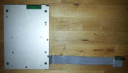
Well, I think to come now with some more details about my LPM.
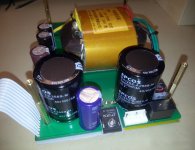
As one could see in the previous pictures, there is about a more professional approach for an serial PSU for Oppo BDP 95, 105 and 105D models.
This LPM is not suitable for the 93 and 103 models, as these models needs few more power rails.
My LPM it have a first power line filtering cell at its input before the main transformer, then a second (cascaded) filtering cell for the power designated to the original toroid (analogue PSU of the player). Optional use (choosing) of 115v AC is provided by design. The original 110/220v AC switch is not used. AC voltage input is set it up at the assembly stage.
The PCB is designed to accent both R core transformers, as toroidal ones. If toroid transformers should be used, then it can be one for both rails (5v and 15v), or two, one for 5v rail and one for 15v.
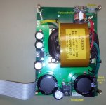
The rectifier stages it use Schottky diodes. For 5vDC rail are used two 8A diodes, so the transformer should deliver 2x6vAC. 15vDC rail it it use two or four Schottky diodes 5A, accordingly to the transformer setup (2x 15vAC, or 1x15vAC).
I decided to use an R core transformer, for its advantages: highest efficiency, and most important, the best HF noise separation/isolation primary/secondary. This type transformer it have the lowest internal capacity, and therefore it transfer lowest level HF noise from its primary winding to the secondary. The toroidal type is worst in this respect. Of course it should not be necessary an power line filter, if a R core transformer is used. However, the PCB is designed so, especially in case it may be equipped with toroid transformers. I chose to use power filters anyway in this illustrated here PSU, more for experimental reasons.
The regulators used are LT adjustable series 1083 and 1086. The adjustable series of these modern components it offer the possibility to be improved even more their output performances.
The filtering stage it consist of strong capacities of over 100 000µ for 5v rail and over 10000µ for 15v rail. As the 15vDC rail it have to power a relatively low current hungry stage, the filtering capacity for this rail is quite huge, so as it is in my LPM. The filtering for 5v rail it can use two 56 000µ caps or 10 x 10000/20000µ, as the PCB is designed for both options.
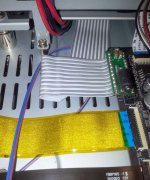
The flat cable used to make the connection LPM - main board is equal balanced for both grounding and hot lines, and it provide an extra filtering for HF noises right on the final adapter for main board connector. This end filtering is meant more to prevent the inducing of HF noises generated buy the digital circuits in main board, back into the power supply. This approach it minimise quite much the overall noise level of the system.
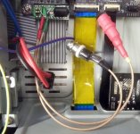
There is a picture here, showing my measurements setup. I realize right now that it was a little bit fault in this setup. I should placed the measurement points before the final filtering cells, but not just on the main board power inputs... However are measured so, the power rails right at the main board input points.
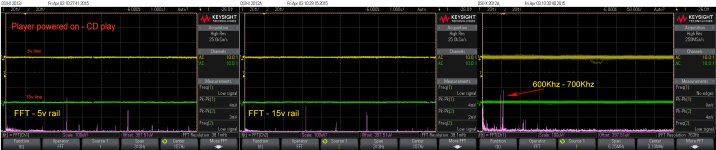
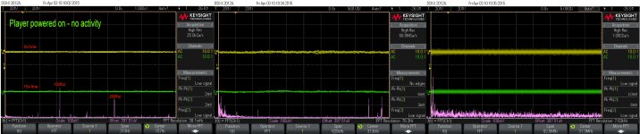
I add here some scope snapshots, using the measurement points as illustrated.
The scope is set it up for high resolution measurements, as this option is much more appropriate for relative low frequencies domain.
The noise levels of the LPM is showed by FFt diagrams, and how is to be seen, it shows around 200µV noise (100Hz ripple and quite few HF picks). The HF picks are induced noises from the digital board.
By adding this quite high quality LPM, the overall improvements for an (already modified player) are important for sound, but the most dramatic impact it have this LPM for the video stage. The image is just exceptional!
As one could see in the previous pictures, there is about a more professional approach for an serial PSU for Oppo BDP 95, 105 and 105D models.
This LPM is not suitable for the 93 and 103 models, as these models needs few more power rails.
My LPM it have a first power line filtering cell at its input before the main transformer, then a second (cascaded) filtering cell for the power designated to the original toroid (analogue PSU of the player). Optional use (choosing) of 115v AC is provided by design. The original 110/220v AC switch is not used. AC voltage input is set it up at the assembly stage.
The PCB is designed to accent both R core transformers, as toroidal ones. If toroid transformers should be used, then it can be one for both rails (5v and 15v), or two, one for 5v rail and one for 15v.
The rectifier stages it use Schottky diodes. For 5vDC rail are used two 8A diodes, so the transformer should deliver 2x6vAC. 15vDC rail it it use two or four Schottky diodes 5A, accordingly to the transformer setup (2x 15vAC, or 1x15vAC).
I decided to use an R core transformer, for its advantages: highest efficiency, and most important, the best HF noise separation/isolation primary/secondary. This type transformer it have the lowest internal capacity, and therefore it transfer lowest level HF noise from its primary winding to the secondary. The toroidal type is worst in this respect. Of course it should not be necessary an power line filter, if a R core transformer is used. However, the PCB is designed so, especially in case it may be equipped with toroid transformers. I chose to use power filters anyway in this illustrated here PSU, more for experimental reasons.
The regulators used are LT adjustable series 1083 and 1086. The adjustable series of these modern components it offer the possibility to be improved even more their output performances.
The filtering stage it consist of strong capacities of over 100 000µ for 5v rail and over 10000µ for 15v rail. As the 15vDC rail it have to power a relatively low current hungry stage, the filtering capacity for this rail is quite huge, so as it is in my LPM. The filtering for 5v rail it can use two 56 000µ caps or 10 x 10000/20000µ, as the PCB is designed for both options.
The flat cable used to make the connection LPM - main board is equal balanced for both grounding and hot lines, and it provide an extra filtering for HF noises right on the final adapter for main board connector. This end filtering is meant more to prevent the inducing of HF noises generated buy the digital circuits in main board, back into the power supply. This approach it minimise quite much the overall noise level of the system.
There is a picture here, showing my measurements setup. I realize right now that it was a little bit fault in this setup. I should placed the measurement points before the final filtering cells, but not just on the main board power inputs... However are measured so, the power rails right at the main board input points.
I add here some scope snapshots, using the measurement points as illustrated.
The scope is set it up for high resolution measurements, as this option is much more appropriate for relative low frequencies domain.
The noise levels of the LPM is showed by FFt diagrams, and how is to be seen, it shows around 200µV noise (100Hz ripple and quite few HF picks). The HF picks are induced noises from the digital board.
By adding this quite high quality LPM, the overall improvements for an (already modified player) are important for sound, but the most dramatic impact it have this LPM for the video stage. The image is just exceptional!
Attachments
-
 Measurements setup.jpg440.8 KB · Views: 166
 -
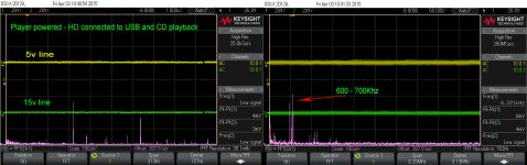 LPM rails while HD on USB and CD playback.jpg479.9 KB · Views: 90
 -
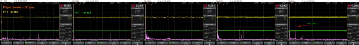 LPM rails on BD playback.jpg676.4 KB · Views: 77
 -
 LPM rails on CD playback.jpg679.1 KB · Views: 94
 -
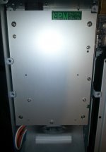
 BD 105 powered by my LPM.jpg692.5 KB · Views: 105
 -
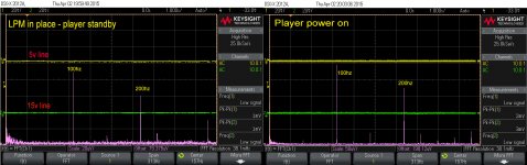 Standby-Power on.jpg466.3 KB · Views: 169
Last edited:
I forgot to mention some details about the PCB itself. The circuitry is printed on an double thickness copper foil board, with very large ground and hot line areas/traces.
The design include too an servo power circuit for an ventilation fan. This fan it can be powered from either 5v or 15v rails, and its current it can be adjusted. The fan power stage on LPM board (controlled by the player power up sequence) is carefully filtered and designed to prevent any eventual noises to be induced into the main rails.
Both regulators and the rectifier bridges are thermally connected to the (upper side) heat sink.
Last edited:
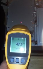
The heat is present, as it is a serial PSU, and it dissipate a little bit. I measured on heat sink, for an relative normal load (player in use, with CD activate, and one HD connected to USB), and the fan running, 48 dg. C. The heat at the cover air output is barely perceptible, while the enclosure air input area is at room temperature.
There is need for a fan to ventilate the enclosure. So as I use the fan set it up, is completely inaudible, but only one put his ear right on the enclosure cover.
The transformer I used for this first edition "Coris LPM" is customized. I intend to improve even more the dissipation amount, so to minimize to lowest as possible the level of heat generation.
Last edited:
- Home
- Source & Line
- Digital Source
- Oppo's BDP105 - discussions, upgrading, mods...