Extremely interesting measurements on ESS DAC.
This chip is not just as the ESS marketing build it its image... Just amazing I may say, and never knew before results revelled here: (in French...)
https://www.youtube.com/watch?v=2QySxRcuPJs
Many thanks to tekko06 for revealing these informations.
I think we may have now an possible explanation for increasing sound quality for this DAC chip, when is overclocked...
Coris, do you understand French?
I do myself, but I realize the language it may be an issue when to get these informations...
Well, there is not so much to see in this video about the measurements environment, as many other details. But I think that now, as the first step is done, another (English) people will may repeat these measurements...
However, some doubts are now switched on in this field...
There are few main conclusions/results out of these measurements:
- The ES9018 it have serious problems when to work over 20bit resolution.
- The same DAC chip it lose the precision and linearity at higher sampling frequencies (over 48Khz). This finding it may explain somehow why ES9018 it may sound better (for someone...
") ), at higher clock frequencies...
), at higher clock frequencies...- The ESS DAC is behind AKM and PCM17xx families, in few of the performances areas.
We may only go further, and let the time to confirm or not the doubts about this so far well appreciated ESS DAC chip.
to Coris!
What ideas do you have for further improvement of the DAC?
Well, at this time nothing new so far...
I think it was touched almost all the interest area for a DAC system (in this case ES9018).
- the powering for DAC rails
- the clock stage, and its powering system
- the post DAC signal processing stage
Assuming the designers did a good job when about the PCB the DAC chip is placed on...
But who knows? Any time it may come a new ideas... From me or somebody else...
Well, a even better SMPS (105 model)...
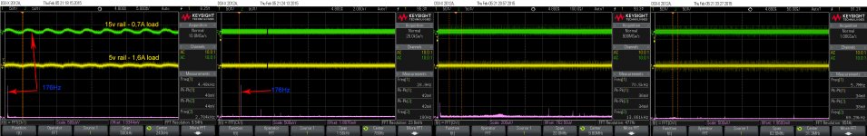
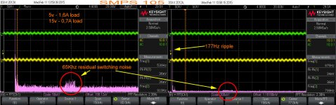
I took a closer look at what and how it can be even more improved this SMPS in Oppo players. Here are the results. FFT is taken for signal on 5v rail. !5v rail is just not so important, as it is used for transport. This line is to be regulated further to 12v on motherboard.
Please observe the spectre (FFTs) of the noise on this one and compare with the previous snapshots, taken on a medium improved device. And even compare it with Oppomod serial PSU (previous pictures).
This SMPS it have now more than half of the noise of the serial PSU. It isn`t nice?
I think it may be a lot of work from now on...
Attachments
Last edited:
Hi,
I just found this great thread.
I don't have the knowledge of you guy's, but nonetheless I'm really enjoying my BDP105D.
The sound was a real upgrade from my previous setup. Another "oddiophile" friend of mine, who knows my system, was also impressed with the sound quality. He has a Electrocompaniet EMC1 Up cd-player, and he brought it over to compare to my OPPO.
To my surprise it was very easy to hear the differences on these to. The OPPO has better detail and analytical skills, but when it comes to brute force, bass weight and slam, the EMC1 crushes the OPPO.
So I started thinking of modding my OPPO, and the more I thought about it, the more tempting it became.
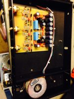
I have pre/power amps from a small Norwegian company called Musical Innovation. I talked to Roar Malmin of Musical Innovation of modding my OPPO, and I will soon get his analog output stage fitted to my OPPO. It is pretty large, so it will be in its own chassis.
So to my question, which other mods would you guys recomend doing on your OPPO's? This is a long thread, with a lot of different mods, it is not possible to do them all....
Here is picture Roar sent me during construction.
I just found this great thread.
I don't have the knowledge of you guy's, but nonetheless I'm really enjoying my BDP105D.
The sound was a real upgrade from my previous setup. Another "oddiophile" friend of mine, who knows my system, was also impressed with the sound quality. He has a Electrocompaniet EMC1 Up cd-player, and he brought it over to compare to my OPPO.
To my surprise it was very easy to hear the differences on these to. The OPPO has better detail and analytical skills, but when it comes to brute force, bass weight and slam, the EMC1 crushes the OPPO.
So I started thinking of modding my OPPO, and the more I thought about it, the more tempting it became.
I have pre/power amps from a small Norwegian company called Musical Innovation. I talked to Roar Malmin of Musical Innovation of modding my OPPO, and I will soon get his analog output stage fitted to my OPPO. It is pretty large, so it will be in its own chassis.
So to my question, which other mods would you guys recomend doing on your OPPO's? This is a long thread, with a lot of different mods, it is not possible to do them all....
Here is picture Roar sent me during construction.
Attachments
Just wondering, thinking to your mod setup. How do you intend to connect these two stages: the DAC in Oppo and the analogue output stage mounted in a different chassis?
Well, cables may be a possible answer... But is the right way to do it? Long cables between DAC differential outputs, and the new output stage? Just asking...
Well, cables may be a possible answer... But is the right way to do it? Long cables between DAC differential outputs, and the new output stage? Just asking...
Yes, I know it's not ideal, Roar also advised against it.
I have to keep the cables as short as possible. but I wanted this mod to be modular.
With these multi-machines, you never know what's coming around the bend. This stage I can easily fit another player in a year or two if there should suddenly be another format...
I have to keep the cables as short as possible. but I wanted this mod to be modular.
With these multi-machines, you never know what's coming around the bend. This stage I can easily fit another player in a year or two if there should suddenly be another format...
As is quite easy to see in this thread, the main focus on modifications and/or improvements it was mainly on the signal processing stages, as clock system.
But not so much focus on an enough important stage of this player: its SMPS.
The modders and the interested users, have proceed to a dramatic tweak in this field: replacing of the original SMPS with a serial PSU which is provided by a far East businessman... At least this replacement is the only modifications the Oppo users have done in this area.
Personally I`m quite sceptical to such PSU replacement. This available on marked serial PSU it suffer first of some design issues, then of some production issues, and finally but most important, a concept issue: it dissipate much heat inside an passive ventilated enough tight enclosure.
Since these Oppo players was launched on marked, I never heard about an improved SMPS for one of the 103 or 105 models. Maybe many tweakers, users, modders did not found anything to improve for this device...
Myself I have to admit, that I never focus on this original PSU, until in the last time...
As I had in hands the SMPSs for both models, I decided to take a closer look on it. I have also previous published some findings in this area, but a really in depth examination I did only in the last days.
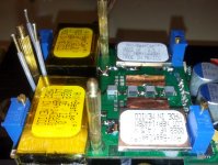
Well, there is enough to be improved here too. These Oppo SMPS are a quite cheap sort of, simple, but it works as it was designed, and are very stable.
After the most possible improvements are done, these devices can even reach a quite high quality level. To improve even further their quality on outputs, one should improve the design itself. So not exactly the case...
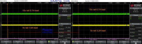
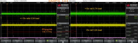
I will further support using of these SMPS for Oppo players, as are the right devices in this case. First of all do not dissipate heat. I loaded the 105 model one with 3,2A + 0,7A, and the 103 model one with 3,2A+0,7A+2x0,5A. No any heating what so ever. Just as it have to be. Very efficient!
These SMPS are switching with 65Khz. As you can see on the pictures here, the residual noises from the main switching frequency are extremely low on outputs: 50µV.
The main noise on these SMPS is the ripple. This ripple can not be eliminated completely. It have a 176-177Hz, and its level is function the loads on one or all rails. One may keep in mind that this SMPs deliver a raw power, which it will be further regulated and filtered quite much, in many stages, by the rest of the power system in the players.
You can observe in these pictures here, that the HF noises (pulses from switching process) are quite constant on loads, but there is the ripple level which is load dependent. At least normally.
I have to say that the SMPS for 103 model it looks worst comparing it with the SMPS for 105 model. This is because the 103 model it use more rails, from the same dimensioned HF transformer. This SMPS for 103 model it should be different designed/dimensioned... But here is more about commercial and business rules, and less professional ones...
But the SMPS for 105 models, after improvements it can perform much better, as you can see in the snapshots here.
Quite excited to hear and see (soon) an assembled player, powered by this improved SMPS...
But not so much focus on an enough important stage of this player: its SMPS.
The modders and the interested users, have proceed to a dramatic tweak in this field: replacing of the original SMPS with a serial PSU which is provided by a far East businessman... At least this replacement is the only modifications the Oppo users have done in this area.
Personally I`m quite sceptical to such PSU replacement. This available on marked serial PSU it suffer first of some design issues, then of some production issues, and finally but most important, a concept issue: it dissipate much heat inside an passive ventilated enough tight enclosure.
Since these Oppo players was launched on marked, I never heard about an improved SMPS for one of the 103 or 105 models. Maybe many tweakers, users, modders did not found anything to improve for this device...
Myself I have to admit, that I never focus on this original PSU, until in the last time...
As I had in hands the SMPSs for both models, I decided to take a closer look on it. I have also previous published some findings in this area, but a really in depth examination I did only in the last days.
Well, there is enough to be improved here too. These Oppo SMPS are a quite cheap sort of, simple, but it works as it was designed, and are very stable.
After the most possible improvements are done, these devices can even reach a quite high quality level. To improve even further their quality on outputs, one should improve the design itself. So not exactly the case...
I will further support using of these SMPS for Oppo players, as are the right devices in this case. First of all do not dissipate heat. I loaded the 105 model one with 3,2A + 0,7A, and the 103 model one with 3,2A+0,7A+2x0,5A. No any heating what so ever. Just as it have to be. Very efficient!
These SMPS are switching with 65Khz. As you can see on the pictures here, the residual noises from the main switching frequency are extremely low on outputs: 50µV.
The main noise on these SMPS is the ripple. This ripple can not be eliminated completely. It have a 176-177Hz, and its level is function the loads on one or all rails. One may keep in mind that this SMPs deliver a raw power, which it will be further regulated and filtered quite much, in many stages, by the rest of the power system in the players.
You can observe in these pictures here, that the HF noises (pulses from switching process) are quite constant on loads, but there is the ripple level which is load dependent. At least normally.
I have to say that the SMPS for 103 model it looks worst comparing it with the SMPS for 105 model. This is because the 103 model it use more rails, from the same dimensioned HF transformer. This SMPS for 103 model it should be different designed/dimensioned... But here is more about commercial and business rules, and less professional ones...
But the SMPS for 105 models, after improvements it can perform much better, as you can see in the snapshots here.
Quite excited to hear and see (soon) an assembled player, powered by this improved SMPS...
Attachments
Last edited:
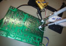
I think I`m not quite satisfied about these remaining HF noises (pictures above)...
It may works to get rid of it. I succeeded for the ones on 15v rail of the 105 SMPS. Still working to fix the 5v rail too.
Quite difficult to improve even more the 103 SMPS, in the same way as the 105 one, because very small available place for some more components... I will see what it can be done...
So, maybe "better" pictures soon...
Yes, your image noise can not but rejoice, that's why I wrote you earlier that SMPS should be replaced by a transformer, which can not be 176 Hz and 65 kHz noise, but the temperature will rise, but how much and how it critical?
Put dry container parallel to each electrolytic capacitor on the output. Deliver higher quality electrolytic capacitors with larger capacity as allow space dimensions. Replace stabilizers less noisy. Use Schottky diodes. That's all that comes to mind.
Put dry container parallel to each electrolytic capacitor on the output. Deliver higher quality electrolytic capacitors with larger capacity as allow space dimensions. Replace stabilizers less noisy. Use Schottky diodes. That's all that comes to mind.
Yes, your image noise can not but rejoice, that's why I wrote you earlier that SMPS should be replaced by a transformer, which can not be 176 Hz and 65 kHz noise, but the temperature will rise, but how much and how it critical?
Put dry container parallel to each electrolytic capacitor on the output. Deliver higher quality electrolytic capacitors with larger capacity as allow space dimensions. Replace stabilizers less noisy. Use Schottky diodes. That's all that comes to mind.
OPPOMOD LPM (for ex.) has ripple too.
This is important to decrease it because you will find it in the audio listening.
Let's compare when Coris would have finalised original tweaked SMPS.
Last edited:
2+2 configuration and XLR Inverted/Normal outputs
I think I have to come back to the dilemma about DAC 2+2 configuration and the XLR polarity settings in the player`s menu.
It was first Joe who warned about an incompatibility between 2+2 configuration and inverted polarity for XLR outputs. He wrote about "no sound" if inverted XLR outputs, with a 2+2 configuration. Well, he had right.
I wrote after that, that this it may not be true, as I could change between "Inverted" and Normal" on a 2+2 configured DAC outputs, and i could not notice any issue as "no sound"...
Well, I had right too.
What is actually the problem with these two contradictory but true findings?
A 2+2 configuration it give "no sound" on Inverted XLR, on the old/first 105 firmwares. Oppo did somehow something in the last firmwares, and there is no more any issue on Inverted/Normal XLR outputs, while a 2+2 configuration for DAC outputs.
BTW, I had the opportunity to compare on the same hardware, an old/first firmware with the last one. The result: huge differences in quality for both picture and sound on the last firmware (on a modded device...).
Oppo may have some smart guys also...
Last edited:
Hi Joe
I do hope you may read (for a while "only" I presume... ) this post...
This story it started in this thread, and now it have to be again continued here... At least, I continued it here with this message/post... There is not OT as it relate to the Oppo player.
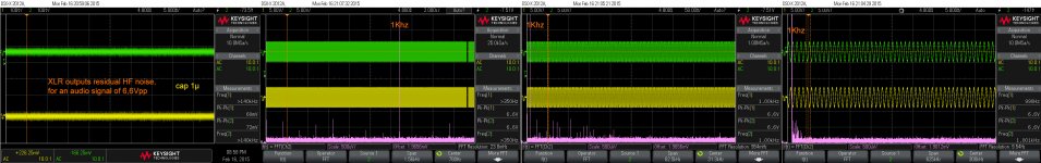
I tried this cap trick again in an improved environment (ES9018 based), after some previous unsuccessful experiments with this DAC chip, but successfully on a PCM1792 one. IT REALLY WORKS! Quite happy to find again out about...
I started this time experimenting with a 1n cap, then 100n, and at last, 1µ. I could notice an remarkable increasing of the soundstage precision/definition, as the cap value increased too. I could also observe that the outputted HF residual noise on DAC phases, it get lower as the cap value increase. So, enough clear the filtering (low-pass) effect when using this cap.
The rest it is showed in the picture here by. Isn`t it nice the FFT?
I do hope you may read (for a while "only" I presume...
) this post...This story it started in this thread, and now it have to be again continued here... At least, I continued it here with this message/post... There is not OT as it relate to the Oppo player.
I tried this cap trick again in an improved environment (ES9018 based), after some previous unsuccessful experiments with this DAC chip, but successfully on a PCM1792 one. IT REALLY WORKS! Quite happy to find again out about...
I started this time experimenting with a 1n cap, then 100n, and at last, 1µ. I could notice an remarkable increasing of the soundstage precision/definition, as the cap value increased too. I could also observe that the outputted HF residual noise on DAC phases, it get lower as the cap value increase. So, enough clear the filtering (low-pass) effect when using this cap.
The rest it is showed in the picture here by. Isn`t it nice the FFT?
Attachments
Last edited:
- Home
- Source & Line
- Digital Source
- Oppo's BDP105 - discussions, upgrading, mods...