Coris!
Do you think it appropriate to apply the operational amplifiers from Burson to further improve stereo? Your opinion?
Well, I have my theory/opinion about these discrete opamps. It may be performing well as opamps, but connecting these quite big PCBs through long wires for power, GND, inputs/outputs, no shielding, it degrade their possible performances.
A device which get these Bursons as improvements, it looks just awful (not only aesthetically, but professional point of view). I will never trust a such system, with these Bursons PCBs hanging all over...
To not say more about the available space these Burson opamps may need into the targeted device...
But at least there is another thing one should pay attention, when appreciate such upgrade: the price. Only one Burson PCb represent an opamp. Do you know how many opamps Oppo player use only for stereo board? Just multiply this with 70$ each Burson, and you may get a very bad budget unbalance...
Definitely not an option these Bursons!
Can you guys clear something up for me.
On the Oppo 103/105 mainboard how is the best way to connect the 27 MHz main clock?
I have come across a few different ways.
From left to right...
On the left is the way suggested by Lee Jaehong. After removal of X2, then also remove C140, R61, R33 and C19. Then connect to points as shown.
On the middle is Joes picture from earlier in this thread.
The last is Joe's recent mod to a Cambridge Audio, which seems to have the clock connected to the empty CN15 block which is above the X2 and further away from the processor.
So my question is, for most direct and best connection, which is the best way? Maybe Joe can chime in with why he has used CN15.
On the Oppo 103/105 mainboard how is the best way to connect the 27 MHz main clock?
I have come across a few different ways.
An externally hosted image should be here but it was not working when we last tested it.
From left to right...
On the left is the way suggested by Lee Jaehong. After removal of X2, then also remove C140, R61, R33 and C19. Then connect to points as shown.
On the middle is Joes picture from earlier in this thread.
The last is Joe's recent mod to a Cambridge Audio, which seems to have the clock connected to the empty CN15 block which is above the X2 and further away from the processor.
So my question is, for most direct and best connection, which is the best way? Maybe Joe can chime in with why he has used CN15.
There is no any difference when to inject the clock signal into the empty CN15, or on one of the old resonator pads. The only thing one have to care is to remove all the adjacent components, which may be connected to the clock inserting point.
The clock signal path should be short as possible, an/or using coaxial cable for long distances.
As the old resonator pads may be thermal stressed by the unsoldering process, there may be better to use the (unused before) CN15 pads.
But maybe Joe can explain better his connection choices...
The clock signal path should be short as possible, an/or using coaxial cable for long distances.
As the old resonator pads may be thermal stressed by the unsoldering process, there may be better to use the (unused before) CN15 pads.
But maybe Joe can explain better his connection choices...
Audiocom ?!
I have recently moded a stereo board "tweaked" before by Audiocom... They painted the whole back side of that 105 stereo board, with a kind of violin varnish, thinking that so it will sounds better... This was a part of the mod pack they offer...
They are funny... is my only comment.
This makes more sense than the mods I have seen proposed in this thread. At least it will prevent oxidation and will do no damage, contrary to funky ideas like placing a clock at a distance, connected with wire. Any idea what the added inductance will do with rise times?
In other words, this is the pot calling the kettle black.
Last edited:
On the middle is Joes picture from earlier in this thread.
That's right! I thought it looked familiar.
")
This makes more sense than the mods I have seen proposed in this thread. At least it will prevent oxidation and will do no damage, contrary to funky ideas like placing a clock at a distance, connected with wire. Any idea what the added inductance will do with rise times?
In other words, this is the pot calling the kettle black.
You right, the oxidation is a big problem for Oppo players...
I can agree, that varnish do not do any harm. Even more it smells very well when to solder over that places...
The problem is somebody pretend doing improvements on "ills" of the Oppo players, and getting paid for an such improvement of a electronic device, by smearing it with violin shellac... Among other things...
The problem is somebody pretend doing improvements on "ills" of the Oppo players, and getting paid for an such improvement of a electronic device, by smearing it with violin shellac... Among other things...
Hi Joe
Yes, I see it now... Well, interesting... First they was not so happy with that title, but now they gave you back the "title"... There is all right for me anyway.
The only I have to observe in this respect, is that I should be noticed somehow by the moderators about a changing done in my title, as it happened when they were not so happy with your name in the previous title... But anyway, I will not make a case of all this.
A little bit out of (this) topic, but I have to say that I got a little bit more sceptical about that cap placed over the phases... I have tried many times, many configurations, and measured the results. Not my intention to give you up, but every time (different configurations), and systematically I got an increasing of the noise levels, as alteration of the shape of the HF noise...
What is very interesting, is that I got that effect using this cap on a PCM1792 DAC. It was that time I supported you (against the rest of the "world"). Since then, I have improved my post DAC stage, and I have got a so soundscene quality, as it was when I used that cap, but without using it now. I have tried to use that cap again on my new and improved post DAC stage: does not work any more. Everything get worse, no matter what cap value I may use.
So, my preliminary conclusion is that it may work the trick with the cap over the phases, in certain configurations for the post DAC stage, and for a quality level of that stage. When one have already the high quality level from that stage, then does not work the trick.
It may be interesting to be done an more detailed research about this case, but I do not have that available time, and my results in the last time it satisfy me, without the help of this trick...
Last edited:
Hi Joe
Yes, I see it now... Well, interesting...
I asked for it to be restored.
I need to see the actual circuit implementation you used, something isn't sounding right, see an actual schematic (confidentially of course, if you so desire). A single cap on its own will not suffice and indeed may well make it worse. I think we may be able to get the magic back happening for you.
A dedicated website is being developed that will deal with the various implementations, ways to do it with "current" and "voltage" DACs, the use of transformers and so on. Also, techniques that can be used to correct for any desired response of a Delta-Sigma DAC. So, there are a number of things happening behind the scenes right now.
Cheers, Joe
Last edited:
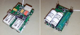
The second version of my AVCC PSU (large decoupling/filtering caps).
It have now visual signalizing for power good (AVCC ready) on power ON sequence. When the indicator get off then the AVCC is at its right/stable level.
The same indicator it will light at power OFF (caps discharging sequence).
Input for PSU: 4,8v - 6v (previous regulated, in this case the original AVCC rail modified for 5v out).
Outputs: 1,2v fixed (LDLN015/6F), adjustable 3,3v (ADM7151/2,5F)
The relay input of the PSU is to be connected to 5v rail for the digital stage of the device. Discharge circuits protected by resettable fuses.
Attachments
In my opinion it may not be advisable to go too high in the values of these supercaps. There are some disadvantages when using too high values. First is the increasing of charging time, and also discharging time... Second it may come the too big dimensions of these Farad capacities, and then it may not be significant improvements for the PSU functionality.
Hopefully it works well to power this way the ES9018 analogue power rails, but the quite long charging/discharging time is the biggest problem when using such capacities...
Hopefully it works well to power this way the ES9018 analogue power rails, but the quite long charging/discharging time is the biggest problem when using such capacities...
When the PSU is connected into the player, the charging time is approx. 40s, and discharging time a little bit longer (around 1 min). Mainly the charging/start up time for this PSU is defined by the current limitation mechanism of the previous regulator stage.
This PSU must have a pre-regulation stage before it, only for current limitation purposes. Else its start up current pick it reach up to 1,6A...
This PSU must have a pre-regulation stage before it, only for current limitation purposes. Else its start up current pick it reach up to 1,6A...
Last edited:
- Home
- Source & Line
- Digital Source
- Oppo's BDP105 - discussions, upgrading, mods...