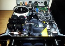
Quite dramatic improvements after changing the power filtering caps...
Oppo had a bad inspiration to not use higher capacities than 4700µ... and using big dimensions 35v capacitors to filter out 7v DC or so... The wrong correlating of the real working tensions, with the caps rated one, leads to an inadequate dimensioning of these caps... Not very impressed by such design...
I will recommend at least doubling of the main filtering capacities, and adapting the caps dimensions to the real needed working tension.
Last edited:
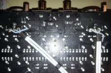
Inspired by Andeas idea about outputting the balanced headphone out to the back panel connectors, I just proceeded to apply this mod.
The concept here is to use the balanced input XLR connectors as outputs ones for the balanced headphone lines.
So, a wire connection have to be made from the front side of the board, to the rear panel. These wires should be shielded, as it runs under the whole PCB. I used silver wires shielded by sliver coated copper bride.
There is still open a question or an unsolved problem about the GND of this "construction"...
There is a big advantage to let the GND connection of the balanced input connectors in place, as for mechanical reasons. In the same time there may be right to take the GND of the headphone balanced output connections from the original designed place (front side of the PCB). Of course the whole GND is common on the whole board, but... This subject it still be open to discussions.
Well, my way to apply this mod were to cut the pins of the balanced input connectors, going into the board, and keep the GND connection in place. Further, the idea is to use the existing holes for these pins, to get through with the wires coming from the front side (headphone balanced out). I do hope it is better understandable this concept by looking at the pictures here.
So, I have cut it the pins, and then unsolder it and extract the cut it part from the board holes. Cleaned up the holes, and got through it with my wires.
The cutting of the pins have to be done "sequential". I mean it have to be cut it the external pin of the balanced input connector, to get then enough place which will permit to cut the second pin.
It is of course no problem to connect the GND of the headphones balanced out, through the shielding brides to the modified balanced input connector on back panel (and isolate it from the input GND area). But in this case the mechanical contact of these connectors with the board it will be weaker.
I think to test this configuration before going further with the right connections. As a line out it may work well as it is done... But my main problem is that I do not have yet a balanced amp... So, the testing it will may wait a while... In between maybe it will be clarified the GND problem in this mod...
Also I`m waiting for opinions/suggestions about this detail.
Attachments
Quite dramatic improvements after changing the power filtering caps...
Oppo had a bad inspiration to not use higher capacities than 4700µ... and using big dimensions 35v capacitors to filter out 7v DC or so... The wrong correlating of the real working tensions, with the caps rated one, leads to an inadequate dimensioning of these caps... Not very impressed by such design...
I will recommend at least doubling of the main filtering capacities, and adapting the caps dimensions to the real needed working tension.
Can you please provide a bit more detail on the types of improvements you have heard with this change in the power supply?
Thanks!
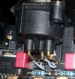
Re ground connection for balanced XLR output:
Usually the ground connection should be connected to the chassis at the entry point.
See for example http://www.rane.com/note110.html
Usually the ground connection should be connected to the chassis at the entry point.
See for example http://www.rane.com/note110.html
Last edited:
Can you please provide a bit more detail on the types of improvements you have heard with this change in the power supply?
Thanks!
There is not easy to describe by text how the sounds it sounds. There is an overall improvement, which is very easy to notice. The clarity of the sound is increased. More details, and very fine details. The bass is even more "heavy" and penetrating. Just amazing! Am increasing in dynamics is also to be noticed. There is another kind of sound quality, than the original device provide.
I have tested so far the DAC stage. And here the suddenly improvement it come very obvious. Is quite surprising how much it mean to have a better power for DAC. At least is only about to filter out the 50Hz noises, and lower the ripple. Well, only this is enough to have another sound quality out of this device.
There are many regulators in the HA-1, and the most of these are low noise. Event hough such low noise regulators wide used in the amplifier, just lowering the ripple on the main power rails, or increase the filtering of this, it mean very much for the resulting sound.
I did only few changes for these filtering caps, as I did not have all the components I needed. I ordered the right caps, and I intend to remove all the so called Oppo made capacitors used in this device.
I have noticed the same improvements after increased the filtering capacities, when about Oppo player series, and its power system. I did not believed Oppo didn`t paid enough attention to this detail in their high end product (HA-1). Well, until I have done it my self...
Only an example: There is used as filtering cap for the power dedicated to the DAC, an 3300µ/35v (quite big as dimensions) capacitor. Only this one for a 7v DC rail... This 7v is used to generate/regulate it to 3,3v and lower... What happen with the rest of volts from 7 to 3,3, or 1,2v or so?. It is is dissipated as heat inside the enclosure... Such use of the energy increase the ripple quite much, when a not enough filtering capacity is provided by design.
I did not paid myself attention to this detail, until the last time. Such filtering is just stupid! Oppo could use for the same physical dimensions of this cap (3300µ for 7v rail), an 10000µ/10v, or even more. Why they did not? Is for sure cheaper to use a 3300µ what so ever quality cap covered by an heat shrink marked with Oppo logo and so... This is only wrong! The replacing of these filtering caps only prove what was done wrong.
And something else: The used totoid it give an 6vAC on the output designated to the DAC stage. This 6vAC mean in DC 8,4v. I found on my device 7,5vDC, after filtering cap. This mean that the toroid output for this stage is wrong dimensioned. This wrong dimensioned delivered AC power, lead to increased ripple. And this ripple is filtered out with a 3300µ cap...
They who can do it, it should apply this modification first of all, to have another kind of high end device: a real one. Just change the all big and inefficient filtering caps with the right ones, of bigger capacity, and right rated working tension.
Someone will ask: well but what happen with the start inrush currents? All this is fixed (limited) by the toroid itself and its start up mechanism. No problem!
P.S. I have noticed also, increasing the filtering capacities, a lowering of the overall temperature of the enclosure. So far, I do not know what it may be the explanation, correlation between these things...
Last edited:
Re ground connection for balanced XLR output:
Usually the ground connection should be connected to the chassis at the entry point.
See for example Sound System Interconnection
This is done already by Oppo, and its design...
I think to come with some more considerations/observations about the power system in HA-1.
I succeed to replace the most of the filtering caps in the device. Already the improvements are very noticeable, as I mentioned previously. The most remarkable is the resolution increasing in the lowest end of the spectre (as normal also...). The very fine details in the bass range are just exceptional. One get the volume and space in the low frequencies. The persecutions instruments are just rich in very fine details, I could never before noticed. Barely audible low frequencies are fully perceived as air vibrations, and it give a very special dimension to the reproduced sound. Just impressive!
The increasing in dynamics is also to be very well noticed.
Well, one may know that my device it have already some other improvements, so, the effect of the this improved filtering it may be more obvious. I do not know how it may be perceived this improvement (better filtering) in a standard device. I do hope some more people it will try this mod (also not a very easy one).
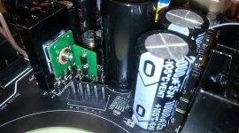
Today I have done some more detailed research about the power system, and I measured quite much.
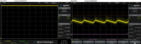
I think to present here an example about the power of the DAC stage. Also a very important stage in this device. I have to say first that unfortunately, I ignored to do some measurements on the unmodified device. I did the measurements on this stage after I have replaced the original filtering cap (3300µ), with a 22000µ one.
The ripple pictured here is with this large capacity installed. The AC line measure 7v, while the DC one (after the rectifier bridge), measure 7,4vDC... This is for sure not right! It indicate a under dimensioned transformer, for the needed current. The result is a quite high ripple, as ripple currents. But why they have to use 7v to generate/regulate it down to 3,3v and lower? It is a very strange approach for a high end audio device design. You can only imagine how the ripple may look like in a standard device with that filtering cap of 3300µ...
There is well known that ES9018 is very sensible at the power quality used to drive it. You can also notice the high frequency noises which still exist over the ripple of this raw 7v for the DAC system...
I have measured also an 20v DC on the power line for the digital board. This 20v it feed a SMPS on board, which deliver 5v DC, used in the most of this board circuits. As it is or regulate it down to 3,3v or lower. Why they have to use 20v to get this 5v DC is enough difficult to understand. It looks like Oppo could not find the right transformer on market or they could not produce a right one with the right AC power lines...
As I have mentioned, the temperature get lower on my device, after changing these caps. The old caps got quite hot, and I though that was because the heat radiations from very close heat sinks. It is very possible that the filtering caps got hot itself, because the very high ripple currents in a wrong dimensioned power system. I can measure now on Class A amp heat sinks 46 dg., on the Class A regulator 42dg, and on the whole enclosure 37dg. The fan inside the enclosure is running, as described previously, and the back panel is placed at approx 3mm distance from the enclosure. I had running the fan before changing the caps, and the overall temperature of the whole device were higher than now...
I succeed to replace the most of the filtering caps in the device. Already the improvements are very noticeable, as I mentioned previously. The most remarkable is the resolution increasing in the lowest end of the spectre (as normal also...). The very fine details in the bass range are just exceptional. One get the volume and space in the low frequencies. The persecutions instruments are just rich in very fine details, I could never before noticed. Barely audible low frequencies are fully perceived as air vibrations, and it give a very special dimension to the reproduced sound. Just impressive!
The increasing in dynamics is also to be very well noticed.
Well, one may know that my device it have already some other improvements, so, the effect of the this improved filtering it may be more obvious. I do not know how it may be perceived this improvement (better filtering) in a standard device. I do hope some more people it will try this mod (also not a very easy one).
Today I have done some more detailed research about the power system, and I measured quite much.
I think to present here an example about the power of the DAC stage. Also a very important stage in this device. I have to say first that unfortunately, I ignored to do some measurements on the unmodified device. I did the measurements on this stage after I have replaced the original filtering cap (3300µ), with a 22000µ one.
The ripple pictured here is with this large capacity installed. The AC line measure 7v, while the DC one (after the rectifier bridge), measure 7,4vDC... This is for sure not right! It indicate a under dimensioned transformer, for the needed current. The result is a quite high ripple, as ripple currents. But why they have to use 7v to generate/regulate it down to 3,3v and lower? It is a very strange approach for a high end audio device design. You can only imagine how the ripple may look like in a standard device with that filtering cap of 3300µ...
There is well known that ES9018 is very sensible at the power quality used to drive it. You can also notice the high frequency noises which still exist over the ripple of this raw 7v for the DAC system...
I have measured also an 20v DC on the power line for the digital board. This 20v it feed a SMPS on board, which deliver 5v DC, used in the most of this board circuits. As it is or regulate it down to 3,3v or lower. Why they have to use 20v to get this 5v DC is enough difficult to understand. It looks like Oppo could not find the right transformer on market or they could not produce a right one with the right AC power lines...
As I have mentioned, the temperature get lower on my device, after changing these caps. The old caps got quite hot, and I though that was because the heat radiations from very close heat sinks. It is very possible that the filtering caps got hot itself, because the very high ripple currents in a wrong dimensioned power system. I can measure now on Class A amp heat sinks 46 dg., on the Class A regulator 42dg, and on the whole enclosure 37dg. The fan inside the enclosure is running, as described previously, and the back panel is placed at approx 3mm distance from the enclosure. I had running the fan before changing the caps, and the overall temperature of the whole device were higher than now...
Attachments
Last edited:
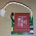
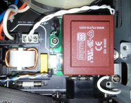
The fan inside the HA-1 enclosure it get now a more properly modification.
The concept here is to use a right transformer to power the fan, while leaving the remote output free to be used as it was designed.
The adaptor module can be seen here. A signal connection from the Remote Out it will activate the small relay for fan power. The transformer it will provide also power to the the battery charger of my (soon coming) mod: battery powered clock board. This board it will provide clock signals for DAC, and the asynchronous USB (re-clocking) circuit.
Attachments
Last edited:
I have to rectify a wrong information presented here.
After a closer examination of the involved circuits, I found out that actually, the small transformer beside the toroid it provide power for standby stage in the HA-1, but not for Remote circuits.
The remote stage of the device is specified for delivering 100mA, but actually for this output is used a 2A capable regulator. Well, the absence of a good heat sink for this regulator it lower its capabilities to deliver important currents. So, we may take as real what the 12v Remote output is specified for.
Well, I was quite quiet in the last time… Doing enough intense work on HA-1…
I had an accident with it and suddenly my extended modified HA-1 would not want to start any more. The ON/OFF button was just ineffective (do not think at the fuse…).
Quite dramatic and scary…
The standby tension was wrong (too low hopefully), and the whole stage was not functioning. I had to fix it, and I did it finally. Not easy at all, and enough demanding, as no any design information is available for this device. In addition, no way to send it back to Oppo…
Fortunately, it was wrong only the standby stage, with enough, many faulty components. Finally, I cannot say that I had not a finger into this damage…
At least this very unhappy situation it had a positive part in it: I had to try to find out how Oppo did its design, and how it may works in details. About some things, I found it out, about other not (yet…). Some other mods are now in place (as increasing/improved the overall dynamic range of the HA-1), because a little bit more knowledge accumulated with this occasion…
I think to share some of my findings, about some stages of the power system of this device, after I have analysed it quite much.
First remark: the HA-1 is a very robust device. It is a very well protected system by design.
As I mentioned before, the power system in this amplifier is enough sophisticated. I found out that the design it have original ideas, and is very well do it.
I just think that Oppo should come out with some general descriptions about part of the system, because it can show how much good work is involved in this product, by really professional designers.
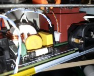
Some people who chosen to look inside the enclosure, have maybe noticed that the toroid transformer it have three wires for primary winding.
Two ends of the primary winding are coupled sequential to the main AC power, by two relays. It was chosen this way to prevent an enough high inrush current, the toroid transformers are known for, when to be connected to the main power. The main processor, or specialized logical circuits, activate the relays in a very precise time sequence at power ON.
For protection reasons, specialized circuits are used to monitor the main power rails of the device. These specialized circuits are just regulators, with some outputs pins used to collect information about the system status.
A very precise shunt regulator reference is used to compare with the obtained information/levels, and decide about eventual faults conditions in the power system of the device.
A protection system based on optocouplers, is designed to monitor inputs or parts in this power area.
A very interesting circuit is that used to regulate the power for Class A stage. It is a kind of differential servo circuit (+/- rails), controlled by high quality opamps (but not the highest quality one…). The inputs of this stage are AC coupled, and it looks to me that are dynamically controlled/shaped in a way, by the audio signal, which goes through the system. This it is my possible explanation, but I cannot state that it is really like this, as I could not found (yet…) the source of the control signals involved in this this regulator system.
Well, I`m quite impressed by the findings so far. It is not easy to find out the functional details of the system, as the most of the traces are inside the board.
About increasing the capacity of the filtering caps, I may say that, while these capacities can be increased quite much just after the rectifier bridges, doing the same with the filtering capacities placed after regulators, it may trigger the protection, when turn ON the device.
A reasonable balance have to be find to have the device working with higher filtering capacities. Increasing these capacities leads to very obviously general improvements for the resulted sound.
The protection it trigger for my device with the large caps I use now, when power ON, but I do not want to lower it, as the sound is just astonishing so. I may find a way to trick this protection… In the meantime, I have just to press the start button two times, to have the device up and going…
I have improved a little bit more the speed of the fan, while keeping it in the inaudible range. I can measure now 36 dg.C for whole enclosure, 42dg.C on Class A heat sinks, and 40dg.C on the Class A regulators heat sinks. Quite nice…
I had an accident with it and suddenly my extended modified HA-1 would not want to start any more. The ON/OFF button was just ineffective (do not think at the fuse…).
Quite dramatic and scary…
The standby tension was wrong (too low hopefully), and the whole stage was not functioning. I had to fix it, and I did it finally. Not easy at all, and enough demanding, as no any design information is available for this device. In addition, no way to send it back to Oppo…
Fortunately, it was wrong only the standby stage, with enough, many faulty components. Finally, I cannot say that I had not a finger into this damage…
At least this very unhappy situation it had a positive part in it: I had to try to find out how Oppo did its design, and how it may works in details. About some things, I found it out, about other not (yet…). Some other mods are now in place (as increasing/improved the overall dynamic range of the HA-1), because a little bit more knowledge accumulated with this occasion…
I think to share some of my findings, about some stages of the power system of this device, after I have analysed it quite much.
First remark: the HA-1 is a very robust device. It is a very well protected system by design.
As I mentioned before, the power system in this amplifier is enough sophisticated. I found out that the design it have original ideas, and is very well do it.
I just think that Oppo should come out with some general descriptions about part of the system, because it can show how much good work is involved in this product, by really professional designers.
Some people who chosen to look inside the enclosure, have maybe noticed that the toroid transformer it have three wires for primary winding.
Two ends of the primary winding are coupled sequential to the main AC power, by two relays. It was chosen this way to prevent an enough high inrush current, the toroid transformers are known for, when to be connected to the main power. The main processor, or specialized logical circuits, activate the relays in a very precise time sequence at power ON.
For protection reasons, specialized circuits are used to monitor the main power rails of the device. These specialized circuits are just regulators, with some outputs pins used to collect information about the system status.
A very precise shunt regulator reference is used to compare with the obtained information/levels, and decide about eventual faults conditions in the power system of the device.
A protection system based on optocouplers, is designed to monitor inputs or parts in this power area.
A very interesting circuit is that used to regulate the power for Class A stage. It is a kind of differential servo circuit (+/- rails), controlled by high quality opamps (but not the highest quality one…). The inputs of this stage are AC coupled, and it looks to me that are dynamically controlled/shaped in a way, by the audio signal, which goes through the system. This it is my possible explanation, but I cannot state that it is really like this, as I could not found (yet…) the source of the control signals involved in this this regulator system.
Well, I`m quite impressed by the findings so far. It is not easy to find out the functional details of the system, as the most of the traces are inside the board.
About increasing the capacity of the filtering caps, I may say that, while these capacities can be increased quite much just after the rectifier bridges, doing the same with the filtering capacities placed after regulators, it may trigger the protection, when turn ON the device.
A reasonable balance have to be find to have the device working with higher filtering capacities. Increasing these capacities leads to very obviously general improvements for the resulted sound.
The protection it trigger for my device with the large caps I use now, when power ON, but I do not want to lower it, as the sound is just astonishing so. I may find a way to trick this protection… In the meantime, I have just to press the start button two times, to have the device up and going…
I have improved a little bit more the speed of the fan, while keeping it in the inaudible range. I can measure now 36 dg.C for whole enclosure, 42dg.C on Class A heat sinks, and 40dg.C on the Class A regulators heat sinks. Quite nice…
Last edited:
As I have mentioned previously, if the clock signal is not present for DAC chip, the HA-1 does not boot.
The immediate logical assertion in such case, is the DAC oscillator it drive too the digital board. Well, it seems that this is not true...
Also one can see that the processors on the digital board it have each its oscillator...
But what it may be the involving of the DAC clock signal in the start up of the device?
I did an experiment and I have isolated the DAC chip from its clock signal (lift it up its clock pin), but the oscillator still being connected as normal. The device did not want start up...
So, the conclusion is that the DAC chip it give a "message" to the rest of the system, making it to boot correctly. But what kind of outputs from ES9018 it may be used for such acknowledgement? For sure not the analogue ones...
I could not see any digital output of the Sabre chip, which it can be used to make known to the system that the chip it have its clock OK, and the start up sequence it can run well.
Anybody with a reasonable explanation at this "mystery"? Maybe Oppo itself...
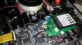
Another important mod for HA-1 is up and running: the battery powered clock board.
The purity of the sound and the precision of sound elements in soundstage are quit impressive. The difference between low noise regulator powered oscillator and battery powered is one more time confirmed for this device too. It sounds different and much better. BTW, 108Mhz SAW oscillator for DAC, and NDK oscillators for asynchronous USB stage.
So far, the mounting of this clock board it may come to end an extended series of modifications for this newest Oppo device. Well, I forgot the changing of the rectifier bridges with Schottky ones. This mod is not done yet, as I`m waiting for the production of designed PCBs adapters...
Attachments
Last edited:
A suggestion for those who may like gimmicks (mods)... dare to do it, and can...
On the HA-1 front panel PCB, just beside of the blue LED, which signalize the power on state of the device, there is a second LED footprint, which is not used/populated.
The DAC chip it have two digital output pins: Automute, and Lock. These pins are not used in HA-1.
One can connect a LED (through a 1k resistor) to GND to get informations from either Lock, or Automute. Automute it may not be a very interesting info, but to know when are lock issues in a file, it may be a usefully information (for someone)...
Further, the LED from Lock pin can be soldered on the unpopulated place for the second LED on front panel, to be well visible. Using the second dimmer level, and 1k resistor for a SMD LED, its light it can predominate over the blue one. Well, one can adjust how one want the light power of this additional LED to visualize the Lock signal from DAC chip (into 8mA).
As the distance from DAC placement and the front panel is enough big, one can use a tin coax cable to transport the signal (the shielding should be connected to GND only on one end). I will recommend exclusive use of Teflon isolated wires for connections inside this hot device.
I may come with more details if somebody will be interested in this...
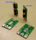
There is available now a Schottky bridge module for replacing the original rectifier bridges in the HA-1. A special designed bridge module, adapted to be mounted on the heatsink in the device (20vDC rail) is already produced and it will be available soon .
The modules it may be available as bare board or fully equipped with two types Schottky diodes, which it fit different power areas in HA-1.
The modules it may be available as bare board or fully equipped with two types Schottky diodes, which it fit different power areas in HA-1.
Attachments
- Status
- This old topic is closed. If you want to reopen this topic, contact a moderator using the "Report Post" button.
- Home
- Source & Line
- Digital Line Level
- OPPO`s HA-1 Headphone amplifier - discussions, upgrading, mods...