Must be..... different ...what are the other markings on the outside? Words etc... ? Definitely weird that it has polarity markings in that case.. Unique construction of some kind. I sent a note to Oppo just asking about basic coupling used...we shall see if they reply ") Like you say.... secret components
Like you say.... secret components
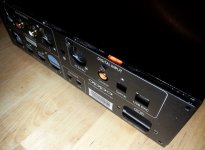
Like you say.... secret components Quite happy with the solution I found for the back panel, giving more access for cold air inside the box. In the last time I had almost an obsession for finding something to improve the ventilation...
It is for sure not the best (looking) one, but I think is enough elegant. It will be Oppo`s job to find a better design to fix this ventilation problem. I have already some alternative in mind, but Im too lazy to put it in a CAD processor...
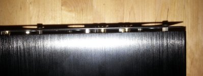
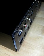
The solution here consist in creating a space in the back of the enclosure, to give more access to the air to come in. This space do not have to contradict very much with the nice design of the device. In my opinion this idea it fit quite well...
Using some (in this case) 5mm lengh M3 spacers for all the holes of the back panel, and the four holes of the enclosure, it create a enough opening. I have not tested it yet, but I think it will work fine this way.
I had not the right screws yet, but I ordered some black ones.
It is for sure not the best (looking) one, but I think is enough elegant. It will be Oppo`s job to find a better design to fix this ventilation problem. I have already some alternative in mind, but Im too lazy to put it in a CAD processor...
The solution here consist in creating a space in the back of the enclosure, to give more access to the air to come in. This space do not have to contradict very much with the nice design of the device. In my opinion this idea it fit quite well...
Using some (in this case) 5mm lengh M3 spacers for all the holes of the back panel, and the four holes of the enclosure, it create a enough opening. I have not tested it yet, but I think it will work fine this way.
I had not the right screws yet, but I ordered some black ones.
Attachments
I shall make a correction to my previous post where I stated about long traces for headphone out. This is not right. After a better examination of the board, I found out about quite short and solid traces from the amplifier output and the headphone connector...
The Class A amplifier is very well monitored by specialized circuits/stage/processor. There is not possible (as I can see so far) to disconnect it from its power system.
Such option it should be provided by design.
The Class A amplifier is very well monitored by specialized circuits/stage/processor. There is not possible (as I can see so far) to disconnect it from its power system.
Such option it should be provided by design.
Any film capacitor of quite small dimensions it may be good. I used SMD type. Value under 0,1µ.
Electrolytic caps can be bipolar if one solder together (serial) two of such - to - or + to +.
The rest of the two legs of the same polarity goes in place on PCB. The advantage of such configuration is half of needed voltage rate for each cap, and reduced dimensions. So (serial), 1000µ/10v + |1000µ/10v = 500µ/20v
And not to forget: short legs as possible when soldered in place.
Coris, I'm sure you that you are aware that although it is true that you can in principle make a bipolar capacitor this way, this is not going to be best for high-quality audio.
jcx,
Certainly, Bateman knows what he's talking about here:
Bateman "Capacitor Sound" articles
"buy Bipolar electros - have full thickness oxide grown on both foils - measures lower distortion than the outdated "back-to-back" polar electrolytics, takes less space too …"
There are many articles and discussions on this topic, but the short answer is to get as high quality output coupling capacitors as possible. If you must use electrolytic's, then use specialized ones for audio, and bypass them. If possible, use film capacitors for output coupling.
Eric
Here is about to experiment with something to observe changes or even improvements than the original configuration. I did not stated that this way to do it is the way one have to do to get the highest possible quality circuit or results...
Anyway using caps in such configuration is better than heaving polarised ones.
There is another problem in this particular case. The available place one have available for these components (very limited). High quality bipolar caps are very big as dimensions. Not to talk about prices... It may not be very reasonable to invest in high end components to only experiment with something... One will do so, when is to apply a final high end solution. Defiantly not this case. If one should deal with own design, then yes, one should implement the best solution. but for experimenting reasons, such configuration it may be quite right...
The point here is to be used quite large bipolar capacities, to improve the low spectre pass through. This low end spectre is most affected by AC isolation caps in audio world.
In my experience, using 100µ is far from enough to have good results. In theory and on the paper, 100µ is more than enough to pass low frequencies down to Hz range..
To improve the high spectre one should use also film caps paralleled with these bipolar ones. As I did actually, and suggested in my post.
It can be also the case that polarised caps may fit well in the circuit. I/we do not know so far how the amplifier and its preamplifier stage is build. So in this case is first of all about experimenting, before conclude something and chose the best solution.
One option to experiment is to use such configuration, I described previously.
At least, is just not all the time it fit the theory with the practical life...
What about an owner of this device , who may try actually this way or another one and come here with facts, own observations, comments, solutions?
Last edited:
Testing time...
As the preliminary mods are in place already, a testing should occur... The results so far are (to say it short): WAW, WAW, WAW!!!
To elaborate a little bit more the results: Just spectacular. The precision of every single sound, and its position in the sound scene is just exceptional. I never ever heard a such detailed sound scene. I got actually what I was looking for: the sounds, the instruments, the voices (and even the adjacent noises produced by the singers touching their instruments) are just in front of me, out of the speakers, in the whole room. The voice is so real and the presence of the singer is only amazing.
I use now the class A amplifier output as line source for my power amplifier, and now the real value of such circuit it is shown in full scale. Is just unbelievable the volume and the extreme fidelity of every component of the sound stage. One can hear and well recognize the metallic sound of the tube bells, when is hit it by percussionist, the adjacent vibrations of the piano strings, well differentiated by the main one, and the voice witch is one meter in front of me (well this is depending on original recording...).
Now my decision is taken: the class A amplifier should not be switched off (not possible anyway...). This class A amplifier it give to the sound another dimensions: the feeling of sounds. Is not a joke at all. Every sound it can be feel it as in a concert hall, in the first row. The bass elements of the sounds are so penetrable, deep and detailed, as one feel actually the disclosing of the air at such vibrations. Just as in real. You can hear the foot pedal drum how is hit it with that soft device. Is just possible to hear such details as hearing the way the drummer hit his drum(s), more or less softer or harder. Just amazing! A very real and very high fidelity!
The speakers become in one way anachronic (if I can say so...). The sounds are so real and so "in the room", that is almost broken the logical connection between speakers and the fact that the sounds it come from there...
Very special experience, I may say...
Oppo did not realized what they made/manufactured actually... I meant also all the time that Oppo devices come to its real very high end values ONLY after some (quite simple and common sense) modifications... It was the case of the BD players, and is again now the case with HA-1 (a solid confirmation...). Actually I was sure that it will be like this, when I invested in HA-1. Very nice to have a factual confirmation...
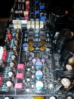
Here is the picture of a part of the visible mods. There are some more which are not yet done, and will be done soon. And the main mod after all these small, but very efficient: the battery powered clock for DAC. I just wonder how it will sounds this device after all will be finished, if the results so far are so spectacular...
P.S. BTW, I used the AC isolation caps of the class A amplifier in the suggested previously mounting configuration (serial coupling) to make a bipolar cap one...
As the preliminary mods are in place already, a testing should occur... The results so far are (to say it short): WAW, WAW, WAW!!!
To elaborate a little bit more the results: Just spectacular. The precision of every single sound, and its position in the sound scene is just exceptional. I never ever heard a such detailed sound scene. I got actually what I was looking for: the sounds, the instruments, the voices (and even the adjacent noises produced by the singers touching their instruments) are just in front of me, out of the speakers, in the whole room. The voice is so real and the presence of the singer is only amazing.
I use now the class A amplifier output as line source for my power amplifier, and now the real value of such circuit it is shown in full scale. Is just unbelievable the volume and the extreme fidelity of every component of the sound stage. One can hear and well recognize the metallic sound of the tube bells, when is hit it by percussionist, the adjacent vibrations of the piano strings, well differentiated by the main one, and the voice witch is one meter in front of me (well this is depending on original recording...).
Now my decision is taken: the class A amplifier should not be switched off (not possible anyway...). This class A amplifier it give to the sound another dimensions: the feeling of sounds. Is not a joke at all. Every sound it can be feel it as in a concert hall, in the first row. The bass elements of the sounds are so penetrable, deep and detailed, as one feel actually the disclosing of the air at such vibrations. Just as in real. You can hear the foot pedal drum how is hit it with that soft device. Is just possible to hear such details as hearing the way the drummer hit his drum(s), more or less softer or harder. Just amazing! A very real and very high fidelity!
The speakers become in one way anachronic (if I can say so...). The sounds are so real and so "in the room", that is almost broken the logical connection between speakers and the fact that the sounds it come from there...
Very special experience, I may say...
Oppo did not realized what they made/manufactured actually... I meant also all the time that Oppo devices come to its real very high end values ONLY after some (quite simple and common sense) modifications... It was the case of the BD players, and is again now the case with HA-1 (a solid confirmation...). Actually I was sure that it will be like this, when I invested in HA-1. Very nice to have a factual confirmation...
Here is the picture of a part of the visible mods. There are some more which are not yet done, and will be done soon. And the main mod after all these small, but very efficient: the battery powered clock for DAC. I just wonder how it will sounds this device after all will be finished, if the results so far are so spectacular...
P.S. BTW, I used the AC isolation caps of the class A amplifier in the suggested previously mounting configuration (serial coupling) to make a bipolar cap one...
Attachments
Last edited:
Great post Coris. Glad it has come around for you after the mods. I am really curious though..did you ever listen to the headamp as as line-out before you started the mods? If so, how much better was just that by itself? This is what was recommended in the review I posted earlier.. I am really wondering how much better that is by itself, baseline, before the added improvements of the mods.
BTW...the specs on the LME49724 differential opamp are extremely good. I am not huge on IC based analog components in general, but I had not seen this part before. I wonder what other devices have employed its use in the market. No doubt it is partly responsible for the highly detailed/fast sound we hear in the HA-1.
Last edited:
Great post Coris. Glad it has come around for you after the mods. I am really curious though..did you ever listen to the headamp as as line-out before you started the mods? If so, how much better was just that by itself? This is what was recommended in the review I posted earlier.. I am really wondering how much better that is by itself, baseline, before the added improvements of the mods.
Yes, I did listen the headphone (as line source) before mods (of course...). In my opinion it was almost no any differences than the normal way to do it. (line out). I did actually this before reading that review.
The difference before/after is very big... After I have noticed the difference at the normal line output, I gave it a listen to the headphone "line", thinking to test the controversial configuration and the improved AC blocking caps.
The performances of the headphone "line" is even more high than what I heard from standard line out.
The same volume, the same dB level on amplifier, it give a tremendous sound when coupled to the headphone output. The quality of the previous stage (DAC in this case) is just amplified many times, at the headphone amp out.
The instinctual reaction of a listener is to increase the volume to "hear" better the details. This in case of a low quality device. When about real hifi, one do not need to increase the volume at all, because it already hear all the details in sounds. The details richness it is perceived by the listener as a level increasing, or sound spatial volume increasing. The detailed perception of the sounds locations in space it make to (perceptual) disappear the real source of the sounds from the sound stage: the speakers. Is just what I experienced testing this improved HA-1...
I think the sound scene can be better appreciated when one use the speakers. This approach is more near reality than using the headphones. With headphones one get the sound stage in his head, and more, one can not feel the pressure of the low frequencies, which in fact it happen in real, when listening instruments/voices. Well, my opinion...
In listening now HA-1 I can locate the instruments in the room space, quite far from speakers. This I can say is quite special, when you perceptual locate an instrument placed at few meters far from speaker... I can notice the small distance between the voices in a vocal duo. Of course, in real these voices can not be in same place. But here is very important how the original recording was engineered, and if voices physical location is transposed into the recording.
Listening a very good recording, I have the feeling to be right in the first row, or at one-two meters far from the main singer/instrument.
Quite surprising experience...
I could locate instruments, listening through HA-1 as it was out of the box, in a sound stage which it was spread behind the speakers line, hearing well the sounds coming out from speaker in that given direction. With this mods in place, the sound scene came out in front of the speakers line, between that line and listener. I have experienced before such effect of hifi with other devices, but using an improved HA-1 this scene become wider and extremely detailed, both in sounds levels and in sounds location in space. Just a pleasure to listen to the music...
I will of course not state that only the replacement of that AC blocking caps at the class A amp input, it leaded to such performances. It may have a contribution to the improvements, together with the another ones.
I was in a way forced to do a series of improvements at once the device was unmounted, because too many operations involved and some difficulties when to mount/unmount the whole thing, after each and every modification...
Yes, indeed LME49724 is a very good performing device. The way to treat the signal differential in all stages using this chip is a very good too.
I have noticed at the DAC stage that this time Oppo used a bunch of transistors in connection with powering of the Sabre chip. I`m not very sure yet about the job of these transistors in power area. I think it may be two explanations. Either these transistors are a quite sophisticated serial regulators system for the power rails of the Sabre chip, or this transistors stage is in fact a monitor for the power lines of the chip. I have seen that Oppo use also in this DAC stage of HA-1, enough large capacities for ES9018 AVCC, and 1,2v line. It may happen that someone at Oppo had an eye on this forum...
The power system for DAC chip as for its clock is much improved, than what was used for the BDP players. But anyway, there is even more place for improvements, as we can see...
Last edited:
Yes, I did listen the headphone (as line source) before mods (of course...). In my opinion it was almost no any differences than the normal way to do it. (line out). I did actually this before reading that review.
The difference before/after is very big... After I have noticed the difference at the normal line output, I gave it a listen to the headphone "line", thinking to test the controversial configuration and the improved AC blocking caps.
The performances of the headphone "line" is even more high than what I heard from standard line out.
The same volume, the same dB level on amplifier, it give a tremendous sound when coupled to the headphone output. The quality of the previous stage (DAC in this case) is just amplified many times, at the headphone amp out.
The instinctual reaction of a listener is to increase the volume to "hear" better the details. This in case of a low quality device. When about real hifi, one do not need to increase the volume at all, because it already hear all the details in sounds. The details richness it is perceived by the listener as a level increasing, or sound spatial volume increasing. The detailed perception of the sounds locations in space it make to (perceptual) disappear the real source of the sounds from the sound stage: the speakers. Is just what I experienced testing this improved HA-1...
I think the sound scene can be better appreciated when one use the speakers. This approach is more near reality than using the headphones. With headphones one get the sound stage in his head, and more, one can not feel the pressure of the low frequencies, which in fact it happen in real, when listening instruments/voices. Well, my opinion...
In listening now HA-1 I can locate the instruments in the room space, quite far from speakers. This I can say is quite special, when you perceptual locate an instrument placed at few meters far from speaker... I can notice the small distance between the voices in a vocal duo. Of course, in real these voices can not be in same place. But here is very important how the original recording was engineered, and if voices physical location is transposed into the recording.
Listening a very good recording, I have the feeling to be right in the first row, or at one-two meters far from the main singer/instrument.
Quite surprising experience...
I could locate instruments, listening through HA-1 as it was out of the box, in a sound stage which it was spread behind the speakers line, hearing well the sounds coming out from speaker in that given direction. With this mods in place, the sound scene came out in front of the speakers line, between that line and listener. I have experienced before such effect of hifi with other devices, but using an improved HA-1 this scene become wider and extremely detailed, both in sounds levels and in sounds location in space. Just a pleasure to listen to the music...
I will of course not state that only the replacement of that AC blocking caps at the class A amp input, it leaded to such performances. It may have a contribution to the improvements, together with the another ones.
I was in a way forced to do a series of improvements at once the device was unmounted, because too many operations involved and some difficulties when to mount/unmount the whole thing, after each and every modification...
Yes, indeed LME49724 is a very good performing device. The way to treat the signal differential in all stages using this chip is a very good too.
I have noticed at the DAC stage that this time Oppo used a bunch of transistors in connection with powering of the Sabre chip. I`m not very sure yet about the job of these transistors in power area. I think it may be two explanations. Either these transistors are a quite sophisticated serial regulators system for the power rails of the Sabre chip, or this transistors stage is in fact a monitor for the power lines of the chip. I have seen that Oppo use also in this DAC stage of HA-1, enough large capacities for ES9018 AVCC, and 1,2v line. It may happen that someone at Oppo had an eye on this forum...
The power system for DAC chip as for its clock is much improved, than what was used for the BDP players. But anyway, there is even more place for improvements, as we can see...
Sounds like if I have to do anything....the coupling capacitor being either bypassed or swapped to a non-polar type + Bypassed with film should make a big difference. As this is the signal path, and everything else you did was peripheral to it. In the past, changing the coupling capacitor unfortunately has always been rather profound for me (going from cheapie electrolytic) --- so I dont doubt what you are hearing one bit. Having non at all, or a well engineered servo circuit is best. Not sure why Oppo didnt know better there when reaching for high-end aspirations with this unit and the headphones that are marketed with it.
Coris, to your points of not being able to experience the impact with headphones vs speakers... well obviously this is the case and it is physics that dictate why. But I can attest... the oppo creates quite a punch through headphones that other units cannot....and it is immediately and profoundly obvious. So we will have to disagree on that one.
Best
It will be interesting to know your results by only replacing the AC blocking caps on the class A amp inputs.
I have also noticed before that Oppo use some kind of special design/ideas in some areas of one of their devices, giving it a high class level, then in the same device they do something quite stupid, using low quality caps or not just the right values, no bypassing in key places, or some other things which looks like contradictory with the goals... Actually this is the meaning of the mods, why there are necessary, and why it fit quite well the Oppo`s products. As one correct what is to be corrected, and keep what is clever done, then the result become a really high class product.
I have also noticed before that Oppo use some kind of special design/ideas in some areas of one of their devices, giving it a high class level, then in the same device they do something quite stupid, using low quality caps or not just the right values, no bypassing in key places, or some other things which looks like contradictory with the goals... Actually this is the meaning of the mods, why there are necessary, and why it fit quite well the Oppo`s products. As one correct what is to be corrected, and keep what is clever done, then the result become a really high class product.
Last edited:
Oppo just replied my email!
Hope it helps someway.
Eduardo,
Sorry for the late replay. In the HA-1 we are using the Texas Instruments LM4562 OP-AMP for the single ended analog outputs and the Texas Instruments LME724 (interchangeable with the OPA1632) OP-AMP for the differential (XLR) analog outputs.
Best Regards,
Customer Service
OPPO Digital, Inc.
Hope it helps someway.
Well, the opamps are a important component in an audio device, but (as I pointed out many times before) there is not the only component to be replaced to get everything right on the top...
BTW, the opamps in the device are of a very good quality. Specially LM49724 and OPA1632. I think for the time being is not necessary to replace the original opamps to improve the performances of HA-1.
I found out recently, in case of HA-1, that it can sounds incredible with some very simple modifications, with its original opamps, power system and so on. I just wonder (as in the case of Oppo BD players, why they did not, or found out itself of, such simple means to increase a lot the performances of their devices. Well, their problem...
I almost finalized a list of the necessary mods for the HA-1 (level one). I will publish this soon, but sorry for not detail it more.
Very soon too, will come a tutorial for disassembling this device. It is not so difficult as it seems to be at the first impression. Everything it just fit perfect mechanically, so assembling/dissembling operations it may be just as easy as it can be.
As the weight of the amplifier it can be reduced dramatically by disassembling it, it can be send it then out the main board for modifications... More details: PM
Last edited:
Well, the opamps are a important component in an audio device, but (as I pointed out many times before) there is not the only component to be replaced to get everything right on the top...
BTW, the opamps in the device are of a very good quality. Specially LM49724 and OPA1632. I think for the time being is not necessary to replace the original opamps to improve the performances of HA-1.
I found out recently, in case of HA-1, that it can sounds incredible with some very simple modifications, with its original opamps, power system and so on. I just wonder (as in the case of Oppo BD players, why they did not, or found out itself of, such simple means to increase a lot the performances of their devices. Well, their problem...
I almost finalized a list of the necessary mods for the HA-1 (level one). I will publish this soon, but sorry for not detail it more.
Very soon too, will come a tutorial for disassembling this device. It is not so difficult as it seems to be at the first impression. Everything it just fit perfect mechanically, so assembling/dissembling operations it may be just as easy as it can be.
As the weight of the amplifier it can be reduced dramatically by disassembling it, it can be send it then out the main board for modifications... More details: PM
I'm really happy to hear that from you. I'll be waiting for a dedicated post with your mods and its pictures. Perhaps you can start an official HA-1's mod thread, haha!
There is also here an enough official thread of mods dedicated to HA-1...
Some of my already done mods are pictured here in some posts. But very detailed pictures about all my mods one may (unfortunately) not expect...
I have in my plans to start my own website specialized in these mods. I just do not have the necessary time to put all this in practice...
As promised, I will try a disassembly tutorial for HA-1.
I will describe in details the operations. For someone many things here it may be already known. The detailed descriptions are for those who may not know such details…
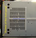
First operation is to unscrew all the screws on the back panel, and remove the back panel plate.
Then, turn the whole device vertically, on a side to have access to the lower side of the enclosure. Carefully remove the rubber pieces on the enclosure`s feet. You may use a tool to lift up the edge of the rubber pieces. These are attached in on the feet, with a double side adhesive tape. You do not have to remove completely the rubber pieces, but only lift it up a half part of it to get access to the inside screws. Unscrew these screws for all the feet.
Under the enclosure`s feet you may find some other screws, as the screws which keep in place the lower grill of the enclosure. Just unscrew all the screws you may find here, and remove the grill.
The down side of the chassis it have some kind of tapes on it to prevent vibrations, and eventual resonances of the mechanical parts (pic 3). If you may remove these tapes, it may be easy to take out the chassis from the enclosure. However, this operation can be done without removing these tapes on the backside of the chassis.
Place the device in normal position with the back end in front of you. Push carefully the inside chassis, while holding the external enclosure in place. The device chassis it is mounted as a tray inside the aluminium enclosure.
When you have created a space between the front panel and the enclosure, by pressing on the back of the chassis, turn the device with its front side in front of you, and pull carefully, but resolute the whole tray, out of the alu enclosure. Done!
You can go even further with the disassembly process, if you may find necessary.
From now on is recommended to use a ESD protection device/system. Such devices sometimes are sold together with computer motherboards, or cabinets. One may also use some conductive mates. Well, some precautions is recommended be taken to avoid ESD problems for the electronic components inside this device. And as a rule, avoid to touch with your fingers the electronic components/chips, if is not really necessary. manipulate the boards from their edges, and do not touch the connectors contacts, or the contacts on the flat cables ends, even when these cables are not connected to the board).
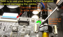
First operation in the next steps is to remove the digital board. Before removing the board, you may disconnect all its connectors. There are few quite easy to remove connectors. The connectors for flat cable it have a locking lid on it, to fix firm in place the flat cable. This lid it have to be lift it up as in pictures (pic 1, 2). The best tool for this operation it may be your fingers.
After the lid is lift it up, the flat cable can be removed very easy. One should pay much attention when to set in place again the flat cable. Its position into the connector is very easy to find, and is quite precise. However, be sure the cable is in the right position, and completely inside the connector, before you lock again up its lid/connector.
You have to take out also the Bluetooth coax from its module on the digital board. There are very small connectors here, so be very carefully when disconnect it. Eventually use a appropriate tool for this operation, and lift up the coax connector as vertical as possible from its pair connector.
After all cables are disconnected from the digital board, you may unscrew the four screws, which hold in place the board.
I will suggest to place then, and keep this digital board into an ESD bag, until it should be mounted again in its place (mounting process).
Next step in disassembly process is to remove the board, which hold on it some of the backside connectors of the amplifier. First, you may take out the white connector, which make the connection between the main board and some of the terminals on the backside of the device. Easy operation and very well visible parts here.
You may then take out the front panel in the next step. First, disconnect the connector with the wires coming from potentiometer.
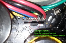
Please pay attention that almost all of these connectors it have a locking mechanism on it (pic 4). One have to press the upper side of this small plastic part against the wires, while pulling out the connector from its place. Some time it may be a difficult operation, but once the connector is out, I will suggest cutting out that small plastic profile which lock up the connector inside. This in case you may appreciate repeating the mounting/disassembling operations. However, there are very few reasons to have these connectors locked in such device. There is actually no any pressure or vibrations to push out these connectors from its places, in absence of a locking system.
After the front panel connector going to the main board is take it out, you can unscrew the four screws, which hold in place this front panel on the chassis. There are two screws on the upper corners of the front panel, and two screws on the opposite side (lower corners – pic 3). To do better this operation, you may want to place the chassis on the edge of a table, with the front panel outside of the table edge. In such case, you may pay attention to hold well the quite heavy front panel while unscrew the last screw from it. Then take carefully out the front panel.
As you may notice at once, that all the mechanical parts in this device it fit very well and precise each in its place. Nothing to be adjusted or a best position to find for a part or another. Everything it have its precise place in the system.
Well, the disassembly process can continue even more.
Now are the internal parts and components in connection with the main board. As the toroid transformer, the small transformer beside the bigger one, the spacers for the digital board and finally, the screws, which hold in place the board on the chassis. After unscrew the nut of the toroid, lift it up holding it with one hand, and with another hand pull out its connectors. So, you may have more place to unlock these connectors, and pull it out (but do not lose the heavy transformer over the board... )
After these screws of the main board are removed, one can take it out. Do not forget to unscrew/disconnect the main GND cable from the chassis.
Be carefully when lift up the main board to gradually remove it from its place out from the chassis. It is placed a piece of cooling tape under the DAC chip, on the backside of the board. The thick tape it may keep like glued the board on the chassis. At least it may be separated quite easy, if one lift up the main board slowly. The main board is big, enough tin, and some components on it are quite heavy. Pay very much attention to not ever bend this big surface PCB, and keep it all the time as flat as possible, holding it from the edges. A very good point to hold it (when in vertical position) is just the hole for toroid transformer. Well, be very carefully to not mechanically stress this big PCB (quite important!). Best is to let it stay in its place/chassis.
Now, after you have disassembled the HA-1 in all its possible components, it rest only to repeat all the operations backwards… Then see if your device it works again…
Well, only a joke. It will of course work well at once you will turn it on (if all the cables/connectors are each in its place).
I will describe in details the operations. For someone many things here it may be already known. The detailed descriptions are for those who may not know such details…
First operation is to unscrew all the screws on the back panel, and remove the back panel plate.
Then, turn the whole device vertically, on a side to have access to the lower side of the enclosure. Carefully remove the rubber pieces on the enclosure`s feet. You may use a tool to lift up the edge of the rubber pieces. These are attached in on the feet, with a double side adhesive tape. You do not have to remove completely the rubber pieces, but only lift it up a half part of it to get access to the inside screws. Unscrew these screws for all the feet.
Under the enclosure`s feet you may find some other screws, as the screws which keep in place the lower grill of the enclosure. Just unscrew all the screws you may find here, and remove the grill.
The down side of the chassis it have some kind of tapes on it to prevent vibrations, and eventual resonances of the mechanical parts (pic 3). If you may remove these tapes, it may be easy to take out the chassis from the enclosure. However, this operation can be done without removing these tapes on the backside of the chassis.
Place the device in normal position with the back end in front of you. Push carefully the inside chassis, while holding the external enclosure in place. The device chassis it is mounted as a tray inside the aluminium enclosure.
When you have created a space between the front panel and the enclosure, by pressing on the back of the chassis, turn the device with its front side in front of you, and pull carefully, but resolute the whole tray, out of the alu enclosure. Done!
You can go even further with the disassembly process, if you may find necessary.
From now on is recommended to use a ESD protection device/system. Such devices sometimes are sold together with computer motherboards, or cabinets. One may also use some conductive mates. Well, some precautions is recommended be taken to avoid ESD problems for the electronic components inside this device. And as a rule, avoid to touch with your fingers the electronic components/chips, if is not really necessary. manipulate the boards from their edges, and do not touch the connectors contacts, or the contacts on the flat cables ends, even when these cables are not connected to the board).
First operation in the next steps is to remove the digital board. Before removing the board, you may disconnect all its connectors. There are few quite easy to remove connectors. The connectors for flat cable it have a locking lid on it, to fix firm in place the flat cable. This lid it have to be lift it up as in pictures (pic 1, 2). The best tool for this operation it may be your fingers.
After the lid is lift it up, the flat cable can be removed very easy. One should pay much attention when to set in place again the flat cable. Its position into the connector is very easy to find, and is quite precise. However, be sure the cable is in the right position, and completely inside the connector, before you lock again up its lid/connector.
You have to take out also the Bluetooth coax from its module on the digital board. There are very small connectors here, so be very carefully when disconnect it. Eventually use a appropriate tool for this operation, and lift up the coax connector as vertical as possible from its pair connector.
After all cables are disconnected from the digital board, you may unscrew the four screws, which hold in place the board.
I will suggest to place then, and keep this digital board into an ESD bag, until it should be mounted again in its place (mounting process).
Next step in disassembly process is to remove the board, which hold on it some of the backside connectors of the amplifier. First, you may take out the white connector, which make the connection between the main board and some of the terminals on the backside of the device. Easy operation and very well visible parts here.
You may then take out the front panel in the next step. First, disconnect the connector with the wires coming from potentiometer.
Please pay attention that almost all of these connectors it have a locking mechanism on it (pic 4). One have to press the upper side of this small plastic part against the wires, while pulling out the connector from its place. Some time it may be a difficult operation, but once the connector is out, I will suggest cutting out that small plastic profile which lock up the connector inside. This in case you may appreciate repeating the mounting/disassembling operations. However, there are very few reasons to have these connectors locked in such device. There is actually no any pressure or vibrations to push out these connectors from its places, in absence of a locking system.
After the front panel connector going to the main board is take it out, you can unscrew the four screws, which hold in place this front panel on the chassis. There are two screws on the upper corners of the front panel, and two screws on the opposite side (lower corners – pic 3). To do better this operation, you may want to place the chassis on the edge of a table, with the front panel outside of the table edge. In such case, you may pay attention to hold well the quite heavy front panel while unscrew the last screw from it. Then take carefully out the front panel.
As you may notice at once, that all the mechanical parts in this device it fit very well and precise each in its place. Nothing to be adjusted or a best position to find for a part or another. Everything it have its precise place in the system.
Well, the disassembly process can continue even more.
Now are the internal parts and components in connection with the main board. As the toroid transformer, the small transformer beside the bigger one, the spacers for the digital board and finally, the screws, which hold in place the board on the chassis. After unscrew the nut of the toroid, lift it up holding it with one hand, and with another hand pull out its connectors. So, you may have more place to unlock these connectors, and pull it out (but do not lose the heavy transformer over the board...
)After these screws of the main board are removed, one can take it out. Do not forget to unscrew/disconnect the main GND cable from the chassis.
Be carefully when lift up the main board to gradually remove it from its place out from the chassis. It is placed a piece of cooling tape under the DAC chip, on the backside of the board. The thick tape it may keep like glued the board on the chassis. At least it may be separated quite easy, if one lift up the main board slowly. The main board is big, enough tin, and some components on it are quite heavy. Pay very much attention to not ever bend this big surface PCB, and keep it all the time as flat as possible, holding it from the edges. A very good point to hold it (when in vertical position) is just the hole for toroid transformer. Well, be very carefully to not mechanically stress this big PCB (quite important!). Best is to let it stay in its place/chassis.
Now, after you have disassembled the HA-1 in all its possible components, it rest only to repeat all the operations backwards… Then see if your device it works again…
Well, only a joke. It will of course work well at once you will turn it on (if all the cables/connectors are each in its place).
Attachments

Last edited:
Well, I`m proud to announce that this last Oppo product (HA-1) is now modified, and the result is a much improved sound. As I know, this it may be the first modification of this Oppo headphone amplifier.
Do you thought the HA-1 it may be the most high level/end of an Oppo device, and no place for more modifications, or improvements? You took wrong. There is here enough to be even more improved...
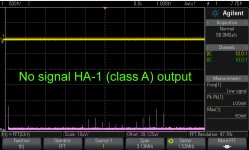
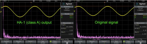
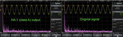
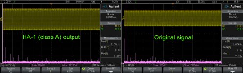
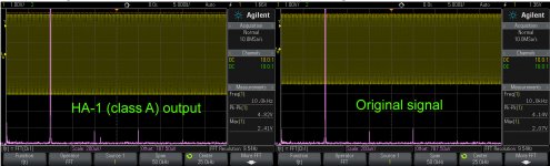
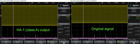
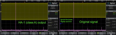
I show here some scope pics, with what I founded, doing some simple measurements. I find these measurements as irrelevant when about sound quality improvements due to quite simple modifications. But for those who want to see some measurements, please have a look...
My signal generator is not a high end one, so I put the original signal beside the measured output of the class A amplifier output, for comparatives. The device level is set to 0dB. I have seen under measurements on my device, 1dB difference between channels (showed by the VU meters). It may be because a graphic display error, or so. I perceive the channels very well balanced.
I show only one and the same channel output. Both channels are very similar.
I use the Vrms for FFT, as this way is more intuitive, I like it better, and I feel it as less abstract than the dB scale. Please note that the FFT calculations are for signal levels in µV domain, while the signal outputted level is in a Vpp equivalent scale.
Sorry to not detailed very much these modifications, and the components values, but a general list of the mods for this so called "Level One Mod" is as follow:
- Applied shielding for some noisy components inside the device (transformer, display. digital board).
- Thermal shield applied to some components (filtering caps) very near high temperature generating devices (heat sinks).
- Improved the passive ventilation and air flow inside the enclosure, by increasing the air input area at the back panel end. A 5 mm space is created between back panel and enclosure, while keeping the same mechanical position for the back panel components.
- Moved the 3,3v regulator`s final transistor on the back side of the main board, to dissipate directly on the entire chassis. This device is a high heat dissipating one in a quite tight and low air flow area.
- Improved the line output to DC coupling.
- Improved the analogue line input and its input AC coupled stage.
- Improved the AC coupled Class A amplifier inputs.
- Improved the decoupling of the line inputs stage, post DAC analogue processing stages, as line output stage. This improvement have as direct consequence an increasing of the filtering capacity for the whole differential power system (+/-14,5v).
- Improved DAC`s I/V stage, while keeping all the original opamps in place.
- Replaced AES/EBU connector with a similar one for headphone output, to use the headphone out (front panel) as dedicated line output.
Level two (to come) will consist mainly in a battery powered clock system for the all clocks in the device: Sabre DAC, and USB asynchronous clocks.
As an option (under developing) it will be a forced ventilation inside the enclosure.
Do you thought the HA-1 it may be the most high level/end of an Oppo device, and no place for more modifications, or improvements? You took wrong. There is here enough to be even more improved...
I show here some scope pics, with what I founded, doing some simple measurements. I find these measurements as irrelevant when about sound quality improvements due to quite simple modifications. But for those who want to see some measurements, please have a look...
My signal generator is not a high end one, so I put the original signal beside the measured output of the class A amplifier output, for comparatives. The device level is set to 0dB. I have seen under measurements on my device, 1dB difference between channels (showed by the VU meters). It may be because a graphic display error, or so. I perceive the channels very well balanced.
I show only one and the same channel output. Both channels are very similar.
I use the Vrms for FFT, as this way is more intuitive, I like it better, and I feel it as less abstract than the dB scale. Please note that the FFT calculations are for signal levels in µV domain, while the signal outputted level is in a Vpp equivalent scale.
Sorry to not detailed very much these modifications, and the components values, but a general list of the mods for this so called "Level One Mod" is as follow:
- Applied shielding for some noisy components inside the device (transformer, display. digital board).
- Thermal shield applied to some components (filtering caps) very near high temperature generating devices (heat sinks).
- Improved the passive ventilation and air flow inside the enclosure, by increasing the air input area at the back panel end. A 5 mm space is created between back panel and enclosure, while keeping the same mechanical position for the back panel components.
- Moved the 3,3v regulator`s final transistor on the back side of the main board, to dissipate directly on the entire chassis. This device is a high heat dissipating one in a quite tight and low air flow area.
- Improved the line output to DC coupling.
- Improved the analogue line input and its input AC coupled stage.
- Improved the AC coupled Class A amplifier inputs.
- Improved the decoupling of the line inputs stage, post DAC analogue processing stages, as line output stage. This improvement have as direct consequence an increasing of the filtering capacity for the whole differential power system (+/-14,5v).
- Improved DAC`s I/V stage, while keeping all the original opamps in place.
- Replaced AES/EBU connector with a similar one for headphone output, to use the headphone out (front panel) as dedicated line output.
Level two (to come) will consist mainly in a battery powered clock system for the all clocks in the device: Sabre DAC, and USB asynchronous clocks.
As an option (under developing) it will be a forced ventilation inside the enclosure.
Attachments
Coris,
Well, we have discussed these measurements before, and with a 12 bit digital oscilloscope, you can't really see much on the audio signals. One option would be to put out a -60 DB signal, and amplify it before you send it to the oscilloscope… I'm glad that it sounds good anyway.
Regarding the heat, have you considered increasing the size of the holes in the bottom of the chassis? Usually, the way the chimney cooling works is to bring the air into the bottom and have it rise up through the top.
You said that you were thinking about forced cooling, and this can be noisy, or dusty if you're not careful. I like the Noctua PC fans, when they are run at lower voltages, ULNA, then they can be truly inaudible. However, I think generally you're better off without any fan at all if possible. Another option would be to add a larger heat sink, or even heat pipe to remove heat from these components.
Eric
Well, I`m proud to announce that this last Oppo product (HA-1) is now modified, and the result is a much improved sound. As I know, this it may be the first modification of this Oppo headphone amplifier.
Do you thought the HA-1 it may be the most high level/end of an Oppo device, and no place for more modifications, or improvements? You took wrong. There is here enough to be even more improved...
I show here some scope pics, with what I founded, doing some simple measurements. I find these measurements as irrelevant when about sound quality improvements due to quite simple modifications. But for those who want to see some measurements, please have a look...
My signal generator is not a high end one, so I put the original signal beside the measured output of the class A amplifier output, for comparatives. The device level is set to 0dB. I have seen under measurements on my device, 1dB difference between channels (showed by the VU meters). It may be because a graphic display error, or so. I perceive the channels very well balanced.
I show only one and the same channel output. Both channels are very similar.
I use the Vrms for FFT, as this way is more intuitive, I like it better, and I feel it as less abstract than the dB scale. Please note that the FFT calculations are for signal levels in µV domain, while the signal outputted level is in a Vpp equivalent scale.
Sorry to not detailed very much these modifications, and the components values, but a general list of the mods for this so called "Level One Mod" is as follow:
- Applied shielding for some noisy components inside the device (transformer, display. digital board).
- Thermal shield applied to some components (filtering caps) very near high temperature generating devices (heat sinks).
- Improved the passive ventilation and air flow inside the enclosure, by increasing the air input area at the back panel end. A 5 mm space is created between back panel and enclosure, while keeping the same mechanical position for the back panel components.
- Moved the 3,3v regulator`s final transistor on the back side of the main board, to dissipate directly on the entire chassis. This device is a high heat dissipating one in a quite tight and low air flow area.
- Improved the line output to DC coupling.
- Improved the analogue line input and its input AC coupled stage.
- Improved the AC coupled Class A amplifier inputs.
- Improved the decoupling of the line inputs stage, post DAC analogue processing stages, as line output stage. This improvement have as direct consequence an increasing of the filtering capacity for the whole differential power system (+/-14,5v).
- Improved DAC`s I/V stage, while keeping all the original opamps in place.
- Replaced AES/EBU connector with a similar one for headphone output, to use the headphone out (front panel) as dedicated line output.
Level two (to come) will consist mainly in a battery powered clock system for the all clocks in the device: Sabre DAC, and USB asynchronous clocks.
As an option (under developing) it will be a forced ventilation inside the enclosure.
Hi Coris,
Thanks for everything. Would it be possible for you to list the parts used (size/type/qty) of capacitors and other details? Not to be prescriptive, but to provide a possible reference point for good results.
Thanks
Jim
- Status
- This old topic is closed. If you want to reopen this topic, contact a moderator using the "Report Post" button.
- Home
- Source & Line
- Digital Line Level
- OPPO`s HA-1 Headphone amplifier - discussions, upgrading, mods...