It's been a few days now and I haven't had time to re open my HA1 and re-clean the internal connectors.
Deoxit has opened up the sound so much on my 2014 OPPO. It's like having better quality music and headphones for free. Next job is collecting materials for shielding, insulating and earthing.
Mu-metal is very expensive.... Got Kapton tape and some steel.. A bit of copper and Aluminium tape. Insulation..
I want Coris to try the deoxit on the internal connectors.. see what he thinks..
Keep smiling and good luck.
Dave
Just an extra... There is one earth point in the chassis from the IEC plug. As this is the main point of contact...
I 1500 grit sanded the chassis and the wire crimp tab washer. I blew out the thread and deoxited the screws wire and washer. It has made a difference but I don't know how or why. This is on top of the earth ground points on the PCB. A wider sound stage...
The Diy'rs cookbook guys on headfi suggested Silclear contact silver grease. Another toy to try...
Good luck
Dave
I stripped the 2 transformers of the oppo.
Then removed all the female wire crimps from the plastic clips. Wasted a scrubbed in IPA to remove the old deoxit.
Then silver soldered the mechanical crimps to give a full interconnect.
I even sanded parts with 2000 grit paper
Clean again and more Deoxit.
14 leads an earth tag. An improved sound and very nice improvement. But a lot of work...
My OPPO, intona , IFIP2 cleaned and soldered connections. A different machine....Thanks Coris...
Dave
Good to see that you do progresses in your mod work...")
As you soldered now the transformers, it may not be very easy to (eventually) send me later your board for the main (and real) mods of the device: replacing the filtering caps, another power system for DAC, battery powered clock system, new configuration for AC coupling caps on inputs, and so on...
However, one may know that the small transformer inside the HA1, do not have anything to do with the sound out of the device. That is for standby power system, and remote +12v stage...
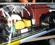
Hereby is a picture of this modded stage. This transformer it provide now power (in addition to its main standby function), to my installed (inaudible) fan, and for the charger of the clocks board (when the device is off).
As you soldered now the transformers, it may not be very easy to (eventually) send me later your board for the main (and real) mods of the device: replacing the filtering caps, another power system for DAC, battery powered clock system, new configuration for AC coupling caps on inputs, and so on...
However, one may know that the small transformer inside the HA1, do not have anything to do with the sound out of the device. That is for standby power system, and remote +12v stage...
Hereby is a picture of this modded stage. This transformer it provide now power (in addition to its main standby function), to my installed (inaudible) fan, and for the charger of the clocks board (when the device is off).
Attachments
Hi Coris, the Soldering is only female wire.
This is not direct to PCB Pins.
The experiment I do is contact resistance.
Every connector has been cleaned inside and earth screws.
For fun I solder the wires with clips for better contact.
I have some silver solder so I try it.
I think people clean cables/ power but never inside....
Warranty issues and a little fear.
This simple CAIG DEOXIT made the sound very good.
But this is just returning to best.
I did not believe people for cables because you fit and remove.
Inside never move unless you are called CORIS.....
I looked at technical reports on metals, oxide, contamination and surface area.
Contact resistance seems to reduce sound quality.
So for fun I try contact cleaners and now MAPLESHADE SILCLEAR SILVER CONTACT GREASE.
Good but very dangerous as it can cause shorts.
First try on uk 3 PIN plug. ..A little too much and tripped main fuse in house.
I need toilet fast..... Angry wife...
So far head phones an new power cable I made.
Positive other than angry wife...
Thanks Coris and good luck
Dave
Well, it came the time (for me) to do something with the post DAC signal processing in HA-1.
I just remove it completely the original one. And replaced it with Lundhal transformers (LL1684).
The simplest approach, with the best ever results. Hopefully, these transformers it fit very well into the available space (after removing the filtering caps in the area).
I preferred to remove the opamps to unload the +/- rails regulators, lowering so a little bit more the heat dissipation.
I have to admit that this passive post DAC signal processing is the best way to connect the DAC outputs to the rest of the amplifying chain. In this case the class A amp inside. This approach it fit very well especially to this device, as it is quite critical the heat dissipation inside its enclosure. The only cons to this mod is the price of the transformers, and a lowering of the overall output level with approx 4 dB. Lower level output is very easy to compensate it from the amplifier. I use now the HA-1 in bypass mode. The sound/result is just in another class of quality...
My device it have now the follow mods:
- improved the whole filtering in power system
- all Schottky rectifier diodes
- improved all the inputs AC coupling
- improved the whole DAC power system
- centralised battery powered clock system
- improved ventilation (active/inaudible)
- and the last one: Lundhal transformers for post DAC signal processing
I think I may stop it her...
A long journey with the HA1 Coris...
If you do more work you will become a blacksmith as I think the only thing left is the case to modify 8 ).
I see now you can maybe do small changes but not big improvements..
How does the headphone output sound to you?
Congratulations on the results so far. Some very good engineering.
Dave
If you do more work you will become a blacksmith as I think the only thing left is the case to modify 8 ).
I see now you can maybe do small changes but not big improvements..
How does the headphone output sound to you?
Congratulations on the results so far. Some very good engineering.
Dave
Yeah... Actually the BDP95/105 are even longer "journeys"...
The enclosure is in fact modified already for my device, concerning the ventilation improvements. To be more precise, it is in fact the way to assembly it. This mod it was in between the first ones, as you may see in the thread`s beginning (the back panel is mounted a little bit away from the rest of the enclosure, using some spacers, to allow more air admission inside).
Big and small improvements are already done, and the last one it was the post DAC processing stage... BTW, I may publish some pictures when I will have a more proff approach for this transformers mod, which is quite an improvisation at this time. The necessary PCBs are already designed.
Now it rest only to wait for the next Oppo models to be issued... But it is very possible at Oppo itself improved their new designs so to not be necessary many other (user) improvements... Let`s see...
The enclosure is in fact modified already for my device, concerning the ventilation improvements. To be more precise, it is in fact the way to assembly it. This mod it was in between the first ones, as you may see in the thread`s beginning (the back panel is mounted a little bit away from the rest of the enclosure, using some spacers, to allow more air admission inside).
Big and small improvements are already done, and the last one it was the post DAC processing stage... BTW, I may publish some pictures when I will have a more proff approach for this transformers mod, which is quite an improvisation at this time. The necessary PCBs are already designed.
Now it rest only to wait for the next Oppo models to be issued...
But it is very possible at Oppo itself improved their new designs so to not be necessary many other (user) improvements... Let`s see...
Last edited:
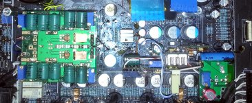
Here it is the fully modded DAC stage in HA-1. Both power system for DAC chip and the post DAC signal processing (using my fully differential module).
The advantage of using active circuits for post DAC processing, over a passive stage (transformers) is the better control (fine adjustments) to fit the inter-stages output/input levels.
I will try to make my customised transformers to fit exactly the levels needed for the best performances. Until such project it will be realised, I prefer to use this active stage. The SQ is however excellent, much better than the original design.
Attachments
I know the Headphone Amp is Class A and it is sonically superior to the line out jacks. I've been doing some testing myself and I can definitely hear an improvement using the Phone out instead of Line out for sound quality. My amp does not have XLR but to test, I installed XLR to RCA adapters on them and tried the XLR output. To my surprise, I found little if any difference between the XLR out and the Phone output. I know the XLR out uses the LME49724 opamp which is different than what is used in the Line out. Of course, I could also be seeing a limitation on my speaker or amp to produce a difference too. I'm wondering if anyone has heard any difference between using the XLR out vs the headphone out as a line source. From what I heard they are practically identical. They are both superior to the Line Out and in my case, using the XLRs leaves the headphone jack alway available for my headphone Thanks!
Thanks!It seems to be a DAC with preamp, but not a headphone amp, as HA-1 it was... At least I appreciate as a better a such only DAC approach, without that heat generating class A amp inside the same enclosure. I also presume the new Oppo DAC it will be based on the new ESS9038pro chip, and so it will be indeed a very high performance/quality product. Well, with the design or production costs limitations Oppo have shown us in its previous products...
How do you open up the HA-1
Indeed, there is not very easy to dismount the device, but this is an impression, only at the first look.
Please go back a little bit into this thread, where you will find my tutorial for dismounting, as some many other things about this device... (post 77)
Well, far from me the intention to give you up, but this modification it may be the very least one to bring some improvement for device resulting signals, or functionality...
You may note that through that IEC, (even made of steel), it goes 230vAC, with a relative low current/power. The resistivity of that 10-15 mm steel things in between is really very insignificant, and most important, it affect the device functionality as low as 0,0000.
Almost the same judgement it apply when about the power cord, in between the device and the wall contact. You may know that the wall contact is very far from being an ideal power source. From that wall connector and further to the power plant there are only huge long wires made of an copper alloy in a best case scenario (this is for mechanical reasons, and on some portion of such network, there are many parts made of steel, aluminium as well). Then are lot of connections with more or less perfect contact, as many transformers with more or less imperfect parameters. The loses in this enormous long connection are quite important, as the lot of noises induced all over. As you use a segment of one or two meters "perfect" conductive wire/cable, made of the purest possible copper or even silver, in the whole that huge electrical network, it have only a enormous insignifiance related to the rest of the system...
If you should follow your approach, by replacing these components (cables, connectors) then you should appreciate to change the wall contact too, and maybe the connection wires inside the wall, and further... Such is just not possible to be done, in a decent reasonable maner...
All this about "perfect" power cords and IEC connectors, are only legends, issued by a kind of businessmen so to they sell something more and better...
If you should proceed at least to open the HA-1 device, then I may suggest you to find some 6-8 mm spacers to place in between the back panel and the rest og the device body/connectors, so to have the back panel placed to a 6-8 mm distance from the enclosure. This space it will allow more air to come inside the enclosure, and it will improve the inside device ventilation. Also placing a fan inside, it will have indeed a real impact for the way the HA-1 it function, and it will extend its life...
My humble opinion/advice...
Last edited:
- Status
- This old topic is closed. If you want to reopen this topic, contact a moderator using the "Report Post" button.
- Home
- Source & Line
- Digital Line Level
- OPPO`s HA-1 Headphone amplifier - discussions, upgrading, mods...