Hola Matias
a short question...did you change the original fuse value? because I'am experimenting with a tentlab scheme for master clock psu , blowing some fuse ......and returning to original configuration !!!???
About capacitors size, I just put two SILMIC II 1000uf/35v in C76,77 ( are really gigantics ) .....some hard mods to the metal case.... but they sound so gooood ( out was Panasonic's FC ) giving me impressive midrange with sweet but incisive tops. I'm going to be a SILMIC's fanatic.....Are very good to tame hardness indeed !!!
An other nice SIL effect is better instrumental separation ( like less intermodulation distortion ) .
For C414,415 more SILMICs ( 100uf/25v ) to improve dynamic .
Keep modding .
Hola Matias
a short question...did you change the original fuse value? because I'am experimenting with a tentlab scheme for master clock psu , blowing some fuse ......and returning to original configuration !!!???
About capacitors size, I just put two SILMIC II 1000uf/35v in C76,77 ( are really gigantics ) .....some hard mods to the metal case.... but they sound so gooood ( out was Panasonic's FC ) giving me impressive midrange with sweet but incisive tops. I'm going to be a SILMIC's fanatic.....Are very good to tame hardness indeed !!!
An other nice SIL effect is better instrumental separation ( like less intermodulation distortion ) .
For C414,415 more SILMICs ( 100uf/25v ) to improve dynamic .
Keep modding .
thanks for the info, at least i know for C77,C76,C402,C403 i can put 1000uf 35v with no problems. The Elnas look good but too big height and width, i might go for the Panasonic FR type which have long life and 105C temp, good specs too and can fit nicely in Dacmagic
cheers
a short question...did you change the original fuse value? because I'am experimenting with a tentlab scheme for master clock psu , blowing some fuse ......and returning to original configuration !!!??? .
Have learned myself after blowing the fuse that the only way to reused the 12VAC rail for a clock PSU is to either a) use a voltage doubler with a limiting power resistor so you bring the voltage down to 25V, or b) re-use the existing voltage doubler in the analog section or c) use a *single* wave rectifier from 12VAC rail or d) use a full-wave rectifier on 12VAC rail **BUT** then you need a high speed digital isolator between Clock GND and Digital GND to avoid shortcircuit and blowing up of the fuse.
I have build a SPICE simulation to experiment on the voltages when mixing the grounds with using rectifiers on the 12VAC.. (bad, bad, bad).
The 2A fuse should be able to handle the additional tentlabs current
I am looking to build GND isolation using ADUM1100 at the to feed the clock signal to the digital section. There is a TexasInstr equivalent with jitter specs down to 1ps which I am also keen to try.
I assume here that the isolator will provide me the benefits of separate clock PSU without the need for a tranformer.
hope this helps
Attachments
Have learned myself after blowing the fuse that the only way to reused the 12VAC rail for a clock PSU is to either a) use a voltage doubler with a limiting power resistor so you bring the voltage down to 25V, or b) re-use the existing voltage doubler in the analog section or c) use a *single* wave rectifier from 12VAC rail or d) use a full-wave rectifier on 12VAC rail **BUT** then you need a high speed digital isolator between Clock GND and Digital GND to avoid shortcircuit and blowing up of the fuse.
Thanks for Your quick replay
may I'll try the simplest way to check the benefit of a separated clock' psu ( my tentlap replica works nicely outside DM ) with a couple of 9v alkaline battery bypassing only bridge diodes and NO FUSE ....and, I suppose, no ground problems.
ciao.
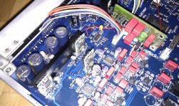
a photo of the NOT WORKING prototype[/URL[/IMG]![p1010007uh.th.jpg]](/community/proxy.php?image=http%3A%2F%2F%5BURL%3Dhttp%3A%2F%2Fimageshack.us%2Fphoto%2Fmy-images%2F822%2Fp1010007uh.jpg%2F%5D%5BIMG%3Dhttp%3A%2F%2Fimg822.imageshack.us%2Fimg822%2F7821%2Fp1010007uh.th.jpg%5D&hash=9f3bc99c389de986cd19ce4aab3db496)
Hi two heads.Hola Matias
a short question...did you change the original fuse value? because I'am experimenting with a tentlab scheme for master clock psu , blowing some fuse ......and returning to original configuration !!!???
About capacitors size, I just put two SILMIC II 1000uf/35v in C76,77 ( are really gigantics ) .....some hard mods to the metal case.... but they sound so gooood ( out was Panasonic's FC ) giving me impressive midrange with sweet but incisive tops. I'm going to be a SILMIC's fanatic.....Are very good to tame hardness indeed !!!
An other nice SIL effect is better instrumental separation ( like less intermodulation distortion ) .
For C414,415 more SILMICs ( 100uf/25v ) to improve dynamic .
Keep modding .
I did not change the original fuse and never had a problem of consumption.
Note that I did not use a clock of the circuit Tentlabs but the pcb Flea Ray.
Consumption would have to measure your clock to see if the cause of the rupture of the fuse.
I do not think that the fuse has been calculated with such fairness. Perhaps there is another mod that is increasing the load.
Typically, a clock consumes 30 to 40 mA.
A hug.
Tanks for help me
my tentlab psu replica has been extensively tested and is ok about power consumption loaded with an oscillator similar the original, but likes to blow fuses....( I don't know if is a TEMPORIZED FUSE eater too....)
I'll try to momentary solve the problem with 2 9v alka battery connected in series, only to have a little taste of clock's mods...
cheap mods, saving for the PLUS....( same case, more functions, and less physical room for big mods We like.....)
un abrazo
marco
OK, but while we are saving money for the new Dacmagic Plus (looks good btw...) may I ask you if anyone tried to run the DM on a good AC filter ?
I just found the User Manual of the new version, DacMagic Plus also here.... but not info on the CA web site.

from the spec ... "Total correlated jitter <130ps"
after all the modding will it worth to replace ?
Last edited:
Replace the 4 things and you will not have doubts.
I still do not understand how not understand the concept of quality in the chain.
There is no modification would not change spots capacitors, opamps, regulators and clock (actually the most influential is the regulation of feeding), that is, attacking the main weaknesses. I still do not understand how some people think that changing one thing will have a hifi DAC. Do not forget that circuit designers have calculated the performance of all components as a whole.
I do not want this message to sound bad, but I call upon reflection.
A hug.
Flea clock installed and the sound improvement is noticeable instrument separation and definition, timing and bass. The stage feels more forward and present. Picture attached.
Thanks to everyone help and Matiasro for the inspiration
Have supplied the Flea Vcc from UNREG2 which measures at 16.8Vdc and sets the 7812 output at 13.5Vdc same as when I powered the circuit with 20Vdc. Hence this makes me assume it is sufficient for the OpAmp operation and 7812 will run cooler.
I couldn't feed the flea from the 7815's input as this measures at 26.7Vdc and the flea input electrolytic (after gyrattor) is rated at 25V hence I decided not to.
That "excessive voltage" led me to another investigation... how to reduce the excessive voltage at both 7x15 input. I tried a 9VAC/3A wall socket which dropped the 7x15 input at 16Vdc and output at 12Vdc which is not right. However should I shortcircuit R400 then 7x15 input raises to 20Vdc which is better than 29Vdc.
Would there be any issue shortcircuit-ing R400, R401 ?
Attachments
Gvlim: Nice nice reform...
Congratulations....! tasted the opa1612?
Haven't tried the opa1612 and I would be interested to follow your OpAmp biasing mod with the JFETs, but I am scared with the SMD soldering work as I have very limited experience there - especially desoldering !
Currently have swapped all OpAmps with LME49720 (was done by a pro)
Can you feed some more info on the opamp mod part ?
The opa1612 sound more natural than 49,720. For my taste the 49720 are very analytical at the cost of naturalness in the instruments.
True, the reform biased opamp requires patience.
You can not imagine what I sweated when soldiers armed adapters (and it was winter).
The main problem is the neighbors (WIMA). Perhaps one possibility is temporarily unsolder.
There are some "help" for desoldering, in my country with a special tin bar stays liquid longer, then you quickly pass the soldering pins above all to keep them warm until they leave.
When it comes to my house (I'm in the office) I'll put the link of a video demonstration.
If it exists in Argentina, the UK should get up in bakeries.
There are some "help" for desoldering, in my country with a special tin bar stays liquid longer, then you quickly pass the soldering pins above all to keep them warm until they leave.
I bought a ChipQuick SMD removal kit which has the flux and the special alloy so I guess I am ready for some sweating myself
Where can I find the schematics to study for the opamp biasing ?
Ok al chipquick, is similar.I bought a ChipQuick SMD removal kit which has the flux and the special alloy so I guess I am ready for some sweating myself
Where can I find the schematics to study for the opamp biasing ?
The information for the biasing:
Biasing Op-Amps into Class A
I bought a ChipQuick SMD removal kit which has the flux and the special alloy so I guess I am ready for some sweating myself
Where can I find the schematics to study for the opamp biasing ?
I use too the Chip-quick, is working great.
As for pushing OpAmps in class A - don't bother, there is nothing to gain. You even "loose" on noise level, because of overheating.
That "excessive voltage" led me to another investigation... how to reduce the excessive voltage at both 7x15 input. I tried a 9VAC/3A wall socket which dropped the 7x15 input at 16Vdc and output at 12Vdc which is not right. However should I shortcircuit R400 then 7x15 input raises to 20Vdc which is better than 29Vdc.
Would there be any issue shortcircuit-ing R400, R401 ?
I shorted R400/R401, connected Flea PS input at U402 Pin1 and powered DACMagic from a 9VAC/3A wall socket.
Results:
1) I got +/- 20Vdc at 7x15 inputs, the temperature effect was massive. Much much cooler U402/U403, *BUT*
2) the flea caused a 2V drop which turned U402 input at 18.6Vdc and output at 14.1Vdc

3) the sound felt as it got some high distortion and lost some clarity
4) reversed mod and went back to original setup. All well
I could get (2) fixed by i) feeding flea from its own Vdoubler or ii) replace R400 to something appropriate, however I will try this along with the Digital isolator - hopefully soon.
Last edited:
I put the dexa regulators in the 7815 and 7915 positions and also put some shinkoh film resistors. changed power supply caps to panasonic FR and digital power supply to rubycon ZLH type. Sounds fantastic, big step up in all areas for dacmagic.
Need now to replace the Bi Polar caps 6pc 10uf 50v, 6pc 470 16v and 2 pc 47uf 16v. Any recomendations? Was thinking Nichihon Muse ES series.
Any help appreciated.
Need now to replace the Bi Polar caps 6pc 10uf 50v, 6pc 470 16v and 2 pc 47uf 16v. Any recomendations? Was thinking Nichihon Muse ES series.
Any help appreciated.
changed power supply caps to panasonic FR and digital power supply to rubycon ZLH type.
Had an interesting experience with replacing the digital power caps (excl. C87,C89 which are on Panasonic FC) to Oscon SP, especially C426,C431,C435.
Oscon SP's on C426/C431 had negative effect to sound experienced in high freq definition and stage separation. LM1117T spec requires lowest ESR at 0.3ohm, so SP Oscon's ESR at 0.06ohm should be the reason. So I went back to the original lytics for C426,C431,C435 which restored the sound to its original clarity.
Noticed ZLH caps ESR is also < 0.6ohm so which caps did you change to their ZLH equivalent ?
- Home
- Source & Line
- Digital Line Level
- Opening the new DacMagic????