2. The relay RL6:B goes to L-OUT, whereas I think it should go to R+OUT. Is this a mistake in the diagram or a design (=manufacturing) error? Could someone check? I'm not upening up my dacmagic for the next couple of days...
Confirmed as a schematic error. On the PCB RL6:B goes to R+OUT.
If you want to do a reform changing only the OPAMP, I recommend to you to replace them for OPA1612. It saw attentivly your photo and specifically the placement of the OPAMPS. I advise you to use less tin because it has too much and can generate oscillations or problems of noise and inclusive of contact.
ok.OPA1612 will not get any noticeable improvement to the already existing LME49720... At that level of performance there are practicaly identic to human ear.
Any other suggestions?
Or is it the generel design that is flawed?
No, the high-performance OpAmps run usually hotter (lower the distortions). But if they are burning your finger they might auto oscillate - clean the solder points with isopropyl alcohol, check the decoupling caps (they need to be 2xSMD, close of OpAmp power terminals).
I am also thinking of putting some aloycoolers on the opamp.
But what do you mean by "2xSMD"? Is it because there are 2 smd's - or?
"2xSMD" are the bypass capacitors already in place.
On another note, the decision to opamp selection should be based on the operational compatibility to the differential filter output stage (XLR out).
Hence I would be interested to understand what are the key spec requirements that we should be looking to match. Recommendations are most welcomed.
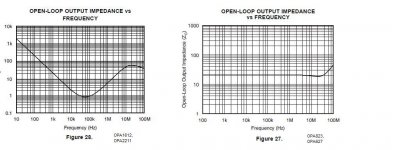
Also, by looking at the attached output impedances which one would be best suited for the XLR out stage ? shouldn't those different response curves be audible ?
On another note, the decision to opamp selection should be based on the operational compatibility to the differential filter output stage (XLR out).
Hence I would be interested to understand what are the key spec requirements that we should be looking to match. Recommendations are most welcomed.
Also, by looking at the attached output impedances which one would be best suited for the XLR out stage ? shouldn't those different response curves be audible ?
Attachments
Found these:
::: Zalman, leading the world of Quiet Computing Solutions :::
Maybe they could give sufficient cooling for Op-amps like LME4986 and LME4972, or at least keep them stable.
::: Zalman, leading the world of Quiet Computing Solutions :::
Maybe they could give sufficient cooling for Op-amps like LME4986 and LME4972, or at least keep them stable.
Choosing and Using Bypass Capacitor
This might be of interest re: "Choosing and Using Bypass Capacitors"
http://www.intersil.com/data/an/an1325.pdf
This might be of interest re: "Choosing and Using Bypass Capacitors"
http://www.intersil.com/data/an/an1325.pdf
Add in parallel the 0.1uF - only if they are good quality ones.do you guys think it will give any improvement if the opamp (ne5532) decoupling caps are increased to 0.1uF?
Add in parallel the 0.1uF - only if they are good quality ones.
i'm thinking of replacing the 0.01 instead, not adding them in parallel
That might leave some HF unfiltered due to change in resonace with PCB traces.
what are you talking about? the decoupling caps is there to strengthen the supply voltage again before it enters the DAC chip. what kind of High Freq??
The small value capacitors are there to provide a supply for any high-frequency loads.
The inductance of the traces is too big for that HF and would generate voltage drops all the way to the power supply. Any pice of PCB trace will act like an inductance and will have a resonance with that capacitor - that's why you want the capacitors as close as possible and with shorter legs - to push that resonance high.
Probably the 0.01uF are ceramics NP0 that have usually that value - you won't find them in 0.1uF easy.
For more details:
http://www.analog.com/static/imported-files/tutorials/MT-101.pdf
http://hsi.web.cern.ch/HSI/s-link/devices/g-ldc/decouple.pdf
Last edited:
Using a X7R in parallel would be better, it will help reduce the resonant peaks and are readily available.
good idea.. put 0.1uF leaded x7r capacitor in parallel to the existing 47nF. thanks!
i have another idea. diode plays a big role as well in gainclone power supply, hence i'm thinking to swap Dacmagic diodes ( D2, D12, D17, D18, D26-D29, D400-D403, D405) with the ultra fast recovery one, with higher current rating (2A, originally 1A from dacmagic)
is it a good idea? if it is, i want to buy these: http://malaysia.rs-online.com/web/p/rectifier/7102964/
Personally I think is overkill, because you have stabilizer IC's after that. In a power amp is different, you don't have that.
so it is still possible? it will not do harm to the circuit, right?
might just order it since the diode i mentioned is pretty cheap
- Home
- Source & Line
- Digital Line Level
- Opening the new DacMagic????