OK, but while we are saving money for the new Dacmagic Plus (looks good btw...) may I ask you if anyone tried to run the DM on a good AC filter ?
I have just connected mine to a cheapie one I brought in a local AV store and the change was terrific in my system.
I was always bothered by the fat mid-upper bass from the DM, but now it's clean and enjoyable. I have connected several other devices (amp, CD player, etc.) to this filter before, but the result was not always pleasing as it was reducing the dynamics, but with the DM just did the right thing. Cleaned up the bass and midrange quite significantly.
Just wondering what a really good AC filter can do to the DM...
I am using a cheapie one too, only for sleeping a little better, because I did not heard many differences like you.
May the transfo that I am using ( 12V/105VA EI type from lighting....) is the cause.
I get good results in mid-bass replacing C419 with 1000uF/16V Silmic II ( lately was Pan FC... ) and solder one 100uF/35V Elna ARD ( gold-black ) across
film caps C298,297 and C329,328 ( you need firm hands and small solder-iron...) .
Dryer and more articulated mid-bass, little more impact in deeper bass too.
I have replaced C271,302 with 100uF/16V Elne Silmic ( the elcaps in the Wolfson's analog 5va PSU )
Another nice mod ( already tested ) for the ones that use std clock, is to solder 2 tant. caps ( 10uF/16V ), one across C32 ( clock psu ) the other across C121 ( Vosc, IC 74VHC14 psu )
Sweeter and airy top hights is the result.
Cheapie mods done while I keep saving for the new DM PLUS...
Happy soldering time.
clock mod
I am getting ready for the clock mod, particularly following Matiasro's approach.
However the clock schematic shows XO1 fed Vcc +5V from the DC-DC filtered output although in the bill of materials XO1 is specified as 3.3V which makes sense as it feeds the 74VHC14 @ 3.3VSCO
Is the schematic wrong ? if XO1 was fed 5Vcc wouldn't this cause 5V straight into 74VHC14 input ? I need to understand what Vcc & Vout specification XO1 must have so to be on the safe side.
Finaly, if I am about the feed the Flea Clock circuit from the 24V found at the 7815's pins 1 + 2, then would there be any issue to connect the flea ground to the XO1's ground (digital ground) ? if yes, how to I avoid mixing virtual and digital grounds ?
Last edited:

I am getting ready for the clock mod, particularly following Matiasro's approach.
Finaly, if I am about the feed the Flea Clock circuit from the 24V found at the 7815's pins 1 + 2, then would there be any issue to connect the flea ground to the XO1's ground (digital ground) ? if yes, how to I avoid mixing virtual and digital grounds ?
Hi amigo
is not good to use analog supply for the clock ( it generate a lot of HF noise ), may you can simply use a bridge rectifier and a low ESR cap ( 470uF/35V should be sufficient..) and connect it at 12AC input ( yes, just after the fuse and before the power switch, having the clock always on, second benefit.....)
Meanwhile have a taste of "clock mod" only soldering a couple of tant caps ( 10uF/25v ) across C32, C121 ( clock psu, IC14 psu ) and let us know your opinion...I think this is a very cheap but effective mod.
Shall solder a 10nF across clock psu pins, too.
About the clock psu voltage, why not check ( whit digital voltmeter....) the real supply after Fb5 ( should be little less than 5v, the schematic is right in my opinion ) to be sure.
Happy mods.
Marco
Thanks Marco,
I was too thinking to feed the flea from the 12VAC however that would not be enough to drive the flea 7812 and OpAmp.
However what about implementing a "voltage doubler replica" (C402,C400,D400,D402) and insert it between C91 and Flea Vin which will feed ~24V straight into 7815 ?
So my plan is to try in steps the performance of
1) Tant cap across C32, C121 & U14
2) flea PSU + "factory" XO Clock with Vin from
a. U402 Dexxa Reg pin 1 & 2
b. own voltage doubler which is fed from 12VAC
3) flea PSU + Crystek Clock with Vin from its
a. U402 Dexxa Reg pin 1 & 2
b. own voltage doubler which is fed from 12VAC
particularly I want to see whether the cost delta between (2) & (3) it really makes the difference.
PS: Crystek ultra low-noise XO specs here: http://www.crystek.com/crystal/spec-sheets/clock/CCHD-957.pdf)
is not good to use analog supply for the clock ( it generate a lot of HF noise ), may you can simply use a bridge rectifier and a low ESR cap ( 470uF/35V should be sufficient..) and connect it at 12AC input ( yes, just after the fuse and before the power switch, having the clock always on, second benefit.....)
I was too thinking to feed the flea from the 12VAC however that would not be enough to drive the flea 7812 and OpAmp.
However what about implementing a "voltage doubler replica" (C402,C400,D400,D402) and insert it between C91 and Flea Vin which will feed ~24V straight into 7815 ?
So my plan is to try in steps the performance of
1) Tant cap across C32, C121 & U14
2) flea PSU + "factory" XO Clock with Vin from
a. U402 Dexxa Reg pin 1 & 2
b. own voltage doubler which is fed from 12VAC
3) flea PSU + Crystek Clock with Vin from its
a. U402 Dexxa Reg pin 1 & 2
b. own voltage doubler which is fed from 12VAC
particularly I want to see whether the cost delta between (2) & (3) it really makes the difference.
PS: Crystek ultra low-noise XO specs here: http://www.crystek.com/crystal/spec-sheets/clock/CCHD-957.pdf)
Last edited:
Thanks Marco,
I was too thinking to feed the flea from the 12VAC however that would not be enough to drive the flea 7812 and OpAmp.
However what about implementing a "voltage doubler replica" (C402,C400,D400,D402) and insert it between C91 and Flea Vin which will feed ~24V straight into 7815 ?
So my plan is to try in steps the performance of
1) Tant cap across C32, C121 & U14
2) flea PSU + "factory" XO Clock with Vin from
a. U402 Dexxa Reg pin 1 & 2
b. own voltage doubler which is fed from 12VAC
3) flea PSU + Crystek Clock with Vin from its
a. U402 Dexxa Reg pin 1 & 2
b. own voltage doubler which is fed from 12VAC
particularly I want to see whether the cost delta between (2) & (3) it really makes the difference.
PS: Crystek ultra low-noise XO specs here: http://www.crystek.com/crystal/spec-sheets/clock/CCHD-957.pdf)
Hola' gvelim
have you already got the FLEA psu ? if not, shall tent lab psu recommended schematic be useful to You ( needs less Vin because start with a 7808 ....)
You can find it on Tent Lab web page .
About regulators : I didn't tried Dexa's, in my DM, Audiocom has changed U404 whit a " specially selected low noise reg " being nothing more than a LM7805 from National Semiconductors...., and I still have 78/7915 for U402/3 ( after them a couple of OSCOM's 10uF/20V from audiocom mod ..!!?? not good for stability low ESR caps after standard reg, isn't it ? ) but, wait a minute, we get an easy solution .... changing them ( C414/415 ) with 2 ELNA ARD 100uF/35V and soldered 4 Elna`s caps ( same value ) across C297/298, C328/329 I have sweeter top hight whit more " authority " in mid/bass range , little more dynamic sound too.
So, whit good bypass on analog rails and better bypass in digital dac's supply C275/303 ( I'am using two 100uF/25V nichicom PSA range, conductive polymer aluminium solid elcaps stuff..) , few nice tants in clock psu, may I don't need "boutique" regulators...really so expensive !!
Will post photos of my dacmagic next week...
Viva cheapie mods !!!
Marco
Hopefully I have corrected my mistakes
1. Replace the output capacitors which are C1/C2 and C40/C41 on the balanced outputs, C293 and C299 on the unbalanced outputs. These are 470uF 16 V, non-polarised electrolytic – I used Michicon Muse ES. Or just short them out by turning the PCB over and soldering a thin wire across each capacitor’s pins. However this DC couples the DACMagic output to the preamp or amp it is plugged into, so consider using a DC voltmeter first to measure the DC offsets on DACMagic and the input you are connecting into.
2. Replace the power supply capacitors for the op amps/analogue circuits. I used Panasonic FC’s as follows:
a. C76, C77, C402, C403 are 1,000uF 50V
b. C414, C415 are 10uF 35V
c. C419 is 1,000uF 35V, I used 1,000uF 50V as 2a above
3. Replace the power supply capacitors for the DSP and DAC digital circuits. I used Rubycon ZA’s and ZLG’s:
a. C424, C425 and C89 are 2,200uF 25V – the first two need to be smaller e.g. ZLG to fit in
b. C87 is 1,000uF 25V, I used 1,000uF 50V as 2a above
c. C8, C10, C25, C26, C31, C35, C45, C130, C426, C431, C435 are 10uF 35V
d. C103 is 100uF 16V
4. Replace the decoupling capacitors around the two WM8740 DAC’s. I used Rubycon ZLG’s:
a. C270, C275, C276 and C301, C303, C304 are all 10uF 35V
b. C271 and C302 are 47uF 35V – I used the DACMagic value and not the 10uF on the WM8740 datasheet
5. Replace the op amps, which are tiny surface mount SO8 packages and on very thin PCB tracks:
a. U55, U56, U59, U60 are NE5532D and can be upgraded to your preference (please see earlier postings about the THD) - I used 4562MA’s
b. U57 and U61 are OP275GS which can be upgraded to 4562MA or your preferred op amps
I left C44, C400 and C401 in place. You can also leave C5 and C212 as they are just the mute/relay supply.
hi, for the panasonic fc caps 1000uf 50v , only ones i can find are 16mm diameter, will these fit in the dacmagic analogue power supply?
cheers
hi, for the panasonic fc caps 1000uf 50v , only ones i can find are 16mm diameter, will these fit in the dacmagic analogue power supply?
cheers
anyone?
I will measure mine, when I come home to night, and write")
thanks very much, measured the originals at 12.5 mm but at all the sites with panasonic caps i find only 16mm, either FC/FM/FR type, although height is okay at 25mm. As i will not be doing the soldering myself i want to order the parts correctly.
ok here is my update..
*Goal*: factory clock upgrade to flea clock
*Status*: Fuse blown, waiting for fuse parts
Not sure what I did wrong which caused the 2A fuse to blow hence I would appreciate some advise on how to proceed.
1) Following on Matiasro's steps I assembled the Flea board with the clock; tested the board with a 20V laptop PSU and all voltages were as they should (3.3V, 24.576MHz)
2) Decided to feed the flea from the 12VAC rail (14V RMS) and used a full rectifier which gives me +19.8VDC which is enough to feed flea's 18V min.
Tested rectifier + flea board and confirmed expected output (3.3V, 24.576Mhz)
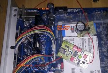
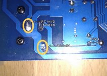
3) Opened DACMagic and looked for the 12AVC rail to feed the rectifier. I measured 14.4VAC between Switch and Ground rail (see picture AC#1/AC#2)
BTW I measured the factory Clock Vcc @ 4.8V, that is between FB5 and ground.
4) Removed "Interquip" oscillator and pluged Flea + Rectifier onto the board, with rectifier taking its VAC as per step (3) above.
Check connectivity and confirmed cable polarity between a) rectifier + flea and b) flea + DAC clock base
5) Powered up.... flea LED light came up followed, nealy instantly, by the FUSE blow up
Any advise on my approach especially from where to get the VAC for the rectifier.
*Goal*: factory clock upgrade to flea clock
*Status*: Fuse blown
, waiting for fuse parts Not sure what I did wrong which caused the 2A fuse to blow hence I would appreciate some advise on how to proceed.
1) Following on Matiasro's steps I assembled the Flea board with the clock; tested the board with a 20V laptop PSU and all voltages were as they should (3.3V, 24.576MHz)
2) Decided to feed the flea from the 12VAC rail (14V RMS) and used a full rectifier which gives me +19.8VDC which is enough to feed flea's 18V min.
Tested rectifier + flea board and confirmed expected output (3.3V, 24.576Mhz)
3) Opened DACMagic and looked for the 12AVC rail to feed the rectifier. I measured 14.4VAC between Switch and Ground rail (see picture AC#1/AC#2)
BTW I measured the factory Clock Vcc @ 4.8V, that is between FB5 and ground.
4) Removed "Interquip" oscillator and pluged Flea + Rectifier onto the board, with rectifier taking its VAC as per step (3) above.
Check connectivity and confirmed cable polarity between a) rectifier + flea and b) flea + DAC clock base
5) Powered up.... flea LED light came up followed, nealy instantly, by the FUSE blow up
Any advise on my approach especially from where to get the VAC for the rectifier.
Attachments
Last edited:
thanks very much, measured the originals at 12.5 mm but at all the sites with panasonic caps i find only 16mm, either FC/FM/FR type, although height is okay at 25mm. As i will not be doing the soldering myself i want to order the parts correctly.
Just measured inside the beast. and Ø16mm should be possible, with some creativity. At least for C76, C77, C402 and C403. But they are placed in pairs, very close to each other. and there are two resistors near by.
Its a 50/50 - I would say. i would personally try it out. but then again, I think the caps are cheap enough to give it a go. So it's up to you to decide
thanks for checking, I would guess it is possible because you cannot get panasonic fc in 12.5mm diam. unless its also 40mm height which then does let you close the case; and i see thats the cap most use in that position. My first stage of mods was done about 2 years ago, i put burson op amps and a 5 volt belleson regulator, now will change the 2 resistors and most caps + dexa 15v regulators. Hope this improves further the dacmagic.
thanks for checking, I would guess it is possible because you cannot get panasonic fc in 12.5mm diam. unless its also 40mm height which then does let you close the case; and i see thats the cap most use in that position. My first stage of mods was done about 2 years ago, i put burson op amps and a 5 volt belleson regulator, now will change the 2 resistors and most caps + dexa 15v regulators. Hope this improves further the dacmagic.
Cool! how did you implement the burson opamps in the 4 small SMD footprints?
or did you "only" change the two, that supply the unbalanced outputs?
Cool! how did you implement the burson opamps in the 4 small SMD footprints?
or did you "only" change the two, that supply the unbalanced outputs?
an electronics engineer did the work, he changed the two for unbalanced output, they had to fit sideways and he said it took 3 hours to fit? I also instructed him to put an 1uf MKP cap on each. They improve sound over the op275 for sure, not sure if its worth the money though.
5) Powered up.... flea LED light came up followed, nealy instantly, by the FUSE blow up
Any advise on my approach especially from where to get the VAC for the rectifier.
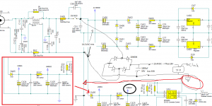
I figured out the full-wave rectifier I introduced short-circuits 12VAC rails when connected the Flea XO GND to the digital GND, hence

 !!
!!I guess I should either a) isolate the Flea_GND from Digital_GND or b) just take the flea voltage from UNREG2/C425
re (a) any ideas ? would this work http://www.farnell.com/datasheets/11701.pdf assuming won't pollute clock with jitter/noise ?
Attachments
I figured out the full-wave rectifier I introduced short-circuits 12VAC rails when connected the Flea XO GND to the digital GND, hence
I guess I should either a) isolate the Flea_GND from Digital_GND or b) just take the flea voltage from UNREG2/C425
re (a) any ideas ? would this work http://www.farnell.com/datasheets/11701.pdf assuming won't pollute clock with jitter/noise ?
I have not read the post came.
For the Flea, I recommend that you feed from the input of U402 (7815).
That way you'll be fine.
A hug.
Matias
Just measured inside the beast. and Ø16mm should be possible, with some creativity. At least for C76, C77, C402 and C403. But they are placed in pairs, very close to each other. and there are two resistors near by.
Its a 50/50 - I would say. i would personally try it out. but then again, I think the caps are cheap enough to give it a go. So it's up to you to decide
Hi Tord
I found panasonic caps at 12.5mm diammeter 1000uf but 35v instead of the 50v, do you think it would work on with this reduction of 15volt?
thanks for any input.
- Home
- Source & Line
- Digital Line Level
- Opening the new DacMagic????