Hi!
If you wire the LL1660 4.5:1 You will loose gain by that factor: 4.5 at the same time output impedance will be redued by that factor squared or about 20! Which is a huge benefit
The 1660 performs and sounds far better in 4.5:1
Well this depends on your system. Nobody can answer this for you without more information. Of course you will need a phono preamp with the proper RIAA eq in additon to such a linestage.
In my opinion the linestage is the wrong place to add gain to the system. ideally the linestage provides a high impedance to the sources. Means to select between sevral sources and a volume control. It should have a low output impedance to drive cables and amps. This is already a demanding task. Asking it to also deliver gain can easily lead to compromises in sound.
The power amp should have an input sensitivity such that it can be easily driven to full output with typical line levels. Phonostages should have the correct gain to bring the signal up to a similar level as the other sources so they can work with the same linestage.
A linestage should just have a little gain maybe 3-6db to have some room left for records with low levels and when you want to crank it up.
Of course you can deviate from this approach if you adapt everything exactly so that the gain structure of the system works for you. In that case you should exactly know what you do.
Best regards
Thomas
Thanks Andy, I have on hand the Lundahl 1660/18mA for #26 tube preamp and wired as you: Alt Q SE Line Output 4.5 : 1 with that configuration have a gain x10 & and output impedance of 2K?
If you wire the LL1660 4.5:1 You will loose gain by that factor: 4.5 at the same time output impedance will be redued by that factor squared or about 20! Which is a huge benefit
The 1660 performs and sounds far better in 4.5:1
can be enough gain for vynils?
Well this depends on your system. Nobody can answer this for you without more information. Of course you will need a phono preamp with the proper RIAA eq in additon to such a linestage.
In my opinion the linestage is the wrong place to add gain to the system. ideally the linestage provides a high impedance to the sources. Means to select between sevral sources and a volume control. It should have a low output impedance to drive cables and amps. This is already a demanding task. Asking it to also deliver gain can easily lead to compromises in sound.
The power amp should have an input sensitivity such that it can be easily driven to full output with typical line levels. Phonostages should have the correct gain to bring the signal up to a similar level as the other sources so they can work with the same linestage.
A linestage should just have a little gain maybe 3-6db to have some room left for records with low levels and when you want to crank it up.
Of course you can deviate from this approach if you adapt everything exactly so that the gain structure of the system works for you. In that case you should exactly know what you do.
Best regards
Thomas
Hi Dave,
The 4П1Л will drive the 6C4C into clipping easily.
It's very well behaved in pentode mode - there are no sharp rises in screen current, even with the anode down at 50V.
.
Thanks but I'm looking at why it couldn't drive a 6C4C/2A3 fairly well in triode mode.
Say I have 4Vrms input from my SS balanced DAC (using an input transformer on the amp):
4vrsmx1.44x2= 11.5 to the 4p1l grid.
My goal is about 1.5 watts max, 1 watt normal listening
with a ccs anode supply should get a gain of at least 8 so:
11.5x8 = 92V's. Divide by 2 gives 45V which is a typical bias for a 2A3. I guess I would rather have a low overall system gain and have the low Ra driving power in triode mode rather than higher gain I won't use in pentode mode.
Am I missing something looking at things this way ? I guess what trade-off am I missing ?
Last edited:
Well, why not. With -45V on the 2A3, you do only need 45V zero-to-peak (=peak voltage)
Ale measured a mu of about 8 for the 4П1Л, so yes, you can clip the 2A3 for, say 6.5V peak, a little over 4V rms.
I don't think you are missing anything, providing the 4V rms from the DAC does not involve any bad-sounding compromises.
Ale measured a mu of about 8 for the 4П1Л, so yes, you can clip the 2A3 for, say 6.5V peak, a little over 4V rms.
I don't think you are missing anything, providing the 4V rms from the DAC does not involve any bad-sounding compromises.
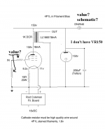
I have DN2540, I only need to know the value in mA to 4P1L and the schematic?
VR150 are these tubes?
vr150 tube | eBay
Recommended brand?
VR150 are these tubes?
vr150 tube | eBay
Recommended brand?
I have DN2540, I only need to know the value in mA to 4P1L and the schematic?
VR150 are these tubes?
vr150 tube | eBay
Recommended brand?
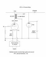
I'm not andy, but yeah, those are the VR150s. I have a bunch of them and they all work regardless of brand, but I have mostly used GE/RCA/american ones. You the CCS needs to provide the 18mA to the 4P1L + whatever current you need to light up the VR150. I don't have the doc in front of me, but close guess is about the same for the shunt as for the circuit. Shunts aren't efficient, but they sound good.
Well, why not. With -45V on the 2A3, you do only need 45V zero-to-peak (=peak voltage)
Ale measured a mu of about 8 for the 4П1Л, so yes, you can clip the 2A3 for, say 6.5V peak, a little over 4V rms.
I don't think you are missing anything, providing the 4V rms from the DAC does not involve any bad-sounding compromises.
Do you see what I'm doing? with a single stage all DHT amp there's opportunity for better 2H & 3H harmonic cancellation if you make the first tube "work" harder and the output tube work less, if it doesn't work of course I can re-wire for pentode mode.
Just going back to the VR150 tube - it's an 0D3 octal base and I put 22.5v through it. So add the 18mA and you get 40mA. I have a 100R resistor followed by a 10uF polypropylene cap before the DN2540, so I adjust the sense resistor on the DN2540 so as to measure 4 volts across the 100 ohm resistor.
Last edited:
How are you going to cancel 3H?
And 2H cancellation by 2 stages is not so straight: curves are multiplied, not summed!
Anode followers are inverting, there is cancellation in a 2 stage SET, maybe we are talking about different topologies ?
I didn't say it would be easy, going all DHT means thinking out of the box and this 4P1L with its high gain and drive allows that. It reminds me have a poor man's EML 20B
If you are interested just run a quick simulation 6n6p vs 6c4Pi driving a 6C4C, no matter what the 6N6P always gives less 2H distortion on the output because its curve shapes are similar to the 6C4C. I know its a just a sim but there has to be some truth to it. I don't find the high gain high mu space age tubes to match well with the older DHTs in the shape of thier curves. I can upload my asc files if anyone is interested.
As far as 3H, cancel isn't the technical term but cancelling 2H leads to less 3H on the output, I would need a chalkboard to show you.
Again this is just a hobby for me, it is supposed to be fun. To me building a canned 5842-2A3 is more like work than fun.
Waveborn if I am wrong let me know, I'm a constant learner
")
Waveborn if I am wrong let me know, I'm a constant learner
In this particular question high school Algebra and trigonometry are needed. As my daughter said, it is part of Advance Math Class. Particularly, what is the difference between summing of functions (P-P stage) and multiplying them (2 stages). How it is reflected on an order of the resulting function.
In this particular question high school Algebra and trigonometry are needed. As my daughter said, it is part of Advance Math Class. Particularly, what is the difference between summing of functions (P-P stage) and multiplying them (2 stages). How it is reflected on an order of the resulting function.
You are assuming the mismatch between the two tube's characteristics is greater than the topology's inversion. Basic math as you said, I think your assumption could be wrong, at least it is according to the simulations, but we both know that the sim tube models aren't perfect. One thing for certain at the same output level if we compare a simple two stage amp:
4p1l-6C4C vs 6c45pi-6C4C the 4P1l has 10dB less distortion according to the math. The 6n6p still beats them both because it has more inverted 2H to cancel the 6C4C's 2H.
My goals with the 4P1L are a little different than most (1-2W into 40 ohms) but it is an interesting discussion.
This is what I am coming up with for a 2W all DHT 4P1L headamp, I think it is worth the cost to try and build (FYI there is more 2H going in the output tube than coming out.)
I am not showing the input transformer. Any feedback appreciated. My design decision is coming down to either this SET or a 4P1L + SS Buffer hybrid.
I am not showing the input transformer. Any feedback appreciated. My design decision is coming down to either this SET or a 4P1L + SS Buffer hybrid.
An externally hosted image should be here but it was not working when we last tested it.
Last edited:
Hi Rod,Hi Andy,
If you don't like fixed bias, it's more than likely the lack of noise rejection (passive solutions), or real noise injection (any regulator with a bandgap reference - i.e. 99% of them).
If you like the bias performance that the Filament Regulators provide, but don't want to deal with the huge power dissipation, you could try separate regulators for each.
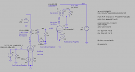
The diagram shows the idea. The Filament is heated normally, and a second regulator provides an adjustable current that is fed into the 50K bias resistor.
0.5mA gives 25V at very low noise - probably 100x lower than typical gas tubes. In fact the noise should be lower than with filament bias, since excess-noise in resistors in often proportional to current.
Recent regulators are temperature-compensated, allowing a stable supply to be developed. Why not give it a try!
Building on your idea, here is my first sketch of a 4P1L into 6C4C (or 4P1L PSE). 4P1L driver is using LL1671 IT in filament bias. The fixed grid bias is using your regulator as suggested above. 6C4C/4P1L PSE with output transformer LL1623/60mA. Looks like a good approach. Couldn't simulate it as the ideal current source used in the IT secondary prevents the AC signal to develop in the grid. Any idea of how to overcome this in LTspice?
Thanks
Ale
Attachments
If you are interested just run a quick simulation 6n6p vs 6c4Pi driving a 6C4C, no matter what the 6N6P always gives less 2H distortion on the output because its curve shapes are similar to the 6C4C. I know its a just a sim but there has to be some truth to it.
Hi Regal,
From my multiple THD tests I found that the 4P1L is unbeatable in terms of linearity (and followed closely by 6C45P and 6e5P. Even 4P1L PSE is slightly more linear than the 6C4C.
I also was puzzled to find out that the 6N6P is not that linear when swinging large signals ( I tested a batch of 10 valves and hopefully I'm not the owner of a poor one!). Please don't take this as the 6N6P doesn't sound good when driving a SE stage, I personally haven't tried it so can't comment on this. Either way, Spice simulation may be tricky sometimes as model may not be that accurate...
Cheers,
Ale
Still missing the concept, the 6n6p distorts more 2H in the model above which results in less 2H on the output. The sim shows it. Basic stuff.
- Home
- Amplifiers
- Tubes / Valves
- One more 4P1L SE