DouglasSelf said:
Hi Bob
I now have a crude thermal model which correlates with the diode temperatures in the LM35 experiment. I have assumed that the die and solder heat capacities are negligible compared with the copper header capacity and that the copper thermal resistance is very low, so that almost all the spec'd thermal resistance junction-to-case (0.694 degC/W) is in the die and solder.
Working empirically from the time/temp curve I get 8.0 J/degC as the header thermal capacity, which is very close to your figure. So far so good.
We know the area of the header (318 mm2) so we can work out the depth of the header that would give 8.0 J/degC. The answer I get is 7.2mm, which is rather regrettably greater than the thickness of the whole package. (5mm)
Clearly something is amiss. Adding the thermal capacity of the plastic doesn't look like it will fix it. Any thoughts?
Hi Doug,
Nice work. I do not have an explanation for the observed discrepency in thermal capacity of the header, but I also recall that the thermal capacity I had to assign the die was larger than had been postulated as well.
See below the status of my current thermal model.
Cheers,
Bob
ThermalTrak thermal model
I have inferred the thermal circuit for the ThermalTrak diode, comprising its thermal resistance from diode junction to header and its thermal mass.
These numbers were estimated by applying a 1 amp current through the diode for several seconds to warm it up to its asymptotic temperature rise above the header. The case was thoroughly heat sinked. The current was then suddenly reduced to a junction measurement current of 10 mA. Diode dissipation during the ON interval was about 0.79 W.
When the high current was removed, I watched the recovery of the diode drop back to its initial cold value. Diode drop immediately following removal of the high current was about 58 mV. The 58 mV change in junction drop, at an estimated 1.7 C/W, corresponds to a junction temperature rise of about 34 C. The time constant for recovery was about 350 ms.
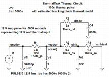
This gives an estimated thermal resistance of 43 C/W and a thermal mass of 8 uF (8 uJ/C). This amount of thermal resistance is surprisingly high, suggesting that OnSemi did not try hard to achieve a tight thermal interface from the junction of the tracking diode to the header. The thermal mass of the diode, at 8 uJ/C, is about ¼ that earlier estimated for the BJT die, so this seems to make sense.
The important point here is that the diode assembly time constant of 350 ms is much shorter than the header assembly time constant of over 6 seconds. This means that the diode will accurately track the header temperature with minimal relative thermal lag.
The thermal model for my experiment is shown below. The heat sink was measured to have a thermal resistance of 1.3 C/W and a thermal mass of 960 J/C (960 Farads in the thermal model). This results in a heat sink time constant of 19 minutes. The heat sink is a finned unit upside-down on the bench, so it is probably operating at a thermal resistance a bit higher than its nominal capability.
Cheers,
Bob
I have inferred the thermal circuit for the ThermalTrak diode, comprising its thermal resistance from diode junction to header and its thermal mass.
These numbers were estimated by applying a 1 amp current through the diode for several seconds to warm it up to its asymptotic temperature rise above the header. The case was thoroughly heat sinked. The current was then suddenly reduced to a junction measurement current of 10 mA. Diode dissipation during the ON interval was about 0.79 W.
When the high current was removed, I watched the recovery of the diode drop back to its initial cold value. Diode drop immediately following removal of the high current was about 58 mV. The 58 mV change in junction drop, at an estimated 1.7 C/W, corresponds to a junction temperature rise of about 34 C. The time constant for recovery was about 350 ms.
This gives an estimated thermal resistance of 43 C/W and a thermal mass of 8 uF (8 uJ/C). This amount of thermal resistance is surprisingly high, suggesting that OnSemi did not try hard to achieve a tight thermal interface from the junction of the tracking diode to the header. The thermal mass of the diode, at 8 uJ/C, is about ¼ that earlier estimated for the BJT die, so this seems to make sense.
The important point here is that the diode assembly time constant of 350 ms is much shorter than the header assembly time constant of over 6 seconds. This means that the diode will accurately track the header temperature with minimal relative thermal lag.
The thermal model for my experiment is shown below. The heat sink was measured to have a thermal resistance of 1.3 C/W and a thermal mass of 960 J/C (960 Farads in the thermal model). This results in a heat sink time constant of 19 minutes. The heat sink is a finned unit upside-down on the bench, so it is probably operating at a thermal resistance a bit higher than its nominal capability.
Cheers,
Bob
Attachments
DouglasSelf said:
Hi John
Could you tell us how thick the copper header is? I'm trying to put together a thermal model that matches the tests I did on Xmas Eve.
One again many thanks for all your hard work.
Douglas,
The transistor is sitting in my office at work. I will return on Jan 5... I'll measure it then.
John
Re: ThermalTrak thermal model
Thanks for the info, Bob. Most ingenious attack on the diode!
I will post my version of the model as soon as I can get it drawn up. I note you are considering the copper header as isothermal, which I think is sound. I modelled it and came up with a Rth of only 0.017 from top to bottom.
However, the apparently impossibly large thermal capacity of the header continues to bother me.
One question: since the spec for Rth juncn-case is 0.694 degC/W, shouldn't your R1 be 0.694 ?
Bob Cordell said:I have inferred the thermal circuit for the ThermalTrak diode, comprising its thermal resistance from diode junction to header and its thermal mass.
These numbers were estimated by applying a 1 amp current through the diode for several seconds to warm it up to its asymptotic temperature rise above the header. The case was thoroughly heat sinked. The current was then suddenly reduced to a junction measurement current of 10 mA. Diode dissipation during the ON interval was about 0.79 W.
When the high current was removed, I watched the recovery of the diode drop back to its initial cold value. Diode drop immediately following removal of the high current was about 58 mV. The 58 mV change in junction drop, at an estimated 1.7 C/W, corresponds to a junction temperature rise of about 34 C. The time constant for recovery was about 350 ms.
This gives an estimated thermal resistance of 43 C/W and a thermal mass of 8 uF (8 uJ/C). This amount of thermal resistance is surprisingly high, suggesting that OnSemi did not try hard to achieve a tight thermal interface from the junction of the tracking diode to the header. The thermal mass of the diode, at 8 uJ/C, is about ¼ that earlier estimated for the BJT die, so this seems to make sense.
The important point here is that the diode assembly time constant of 350 ms is much shorter than the header assembly time constant of over 6 seconds. This means that the diode will accurately track the header temperature with minimal relative thermal lag.
The thermal model for my experiment is shown below. The heat sink was measured to have a thermal resistance of 1.3 C/W and a thermal mass of 960 J/C (960 Farads in the thermal model). This results in a heat sink time constant of 19 minutes. The heat sink is a finned unit upside-down on the bench, so it is probably operating at a thermal resistance a bit higher than its nominal capability.
Cheers,
Bob
Thanks for the info, Bob. Most ingenious attack on the diode!
I will post my version of the model as soon as I can get it drawn up. I note you are considering the copper header as isothermal, which I think is sound. I modelled it and came up with a Rth of only 0.017 from top to bottom.
However, the apparently impossibly large thermal capacity of the header continues to bother me.
One question: since the spec for Rth juncn-case is 0.694 degC/W, shouldn't your R1 be 0.694 ?
Re: Re: ThermalTrak thermal model
Hi Doug,
Yes, for my simplified model here I assumed the copper header is isothermal, and I think that is a pretty good assumption. However, in my earlier post where I had previously modeled an IRFP240 MOSFET with a more distributed model, I did allow for a slight departure from isothermal directly uner the BJT die, but that was just a swag.
Good catch. The number I was using in my ThermalTrak model for Theta jc is definitely wrong, and is a left-over from the IRFP240 model I started with.
Cheers,
Bob
DouglasSelf said:
Thanks for the info, Bob. Most ingenious attack on the diode!
I will post my version of the model as soon as I can get it drawn up. I note you are considering the copper header as isothermal, which I think is sound. I modelled it and came up with a Rth of only 0.017 from top to bottom.
However, the apparently impossibly large thermal capacity of the header continues to bother me.
One question: since the spec for Rth juncn-case is 0.694 degC/W, shouldn't your R1 be 0.694 ?
Hi Doug,
Yes, for my simplified model here I assumed the copper header is isothermal, and I think that is a pretty good assumption. However, in my earlier post where I had previously modeled an IRFP240 MOSFET with a more distributed model, I did allow for a slight departure from isothermal directly uner the BJT die, but that was just a swag.
Good catch. The number I was using in my ThermalTrak model for Theta jc is definitely wrong, and is a left-over from the IRFP240 model I started with.
Cheers,
Bob
Re: Re: Re: ThermalTrak thermal model
Hi Bob
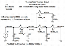
Here is my thermal model, such as it is. You will see that I have concentrated the header mass in the middle of R2 and R3 which represent the thermal resistance of the top and bottom halves of the header respectively. I am running some simulations with it now.
I will try adding your refinements- the junction capacity and the time constant to the diode, but I think they will only affect the short-term dynamics- right now I'm looking at the compensation over 100 seconds.
Bob Cordell said:
Hi Doug,
Yes, for my simplified model here I assumed the copper header is isothermal, and I think that is a pretty good assumption. However, in my earlier post where I had previously modeled an IRFP240 MOSFET with a more distributed model, I did allow for a slight departure from isothermal directly uner the BJT die, but that was just a swag.
Cheers,
Bob
Hi Bob
Here is my thermal model, such as it is. You will see that I have concentrated the header mass in the middle of R2 and R3 which represent the thermal resistance of the top and bottom halves of the header respectively. I am running some simulations with it now.
I will try adding your refinements- the junction capacity and the time constant to the diode, but I think they will only affect the short-term dynamics- right now I'm looking at the compensation over 100 seconds.
Attachments
jgedde said:
Douglas,
The transistor is sitting in my office at work. I will return on Jan 5... I'll measure it then.
John
Many thanks, John. My attempts at a thermal model show it should be 2mm thicker than the whole package, so a reality check is definitely needed...
By the way, thanks for your kind words in #313, but I think you know at least as much about what we're doing here as I do.
Re: Re: Re: Re: ThermalTrak thermal model
Hi Doug,
Nice work. I have updated my LTspice thermal model with the right Theta jc and attached it below.
The curve tracer data that John has provided has also provided good insight into what is going on in these devices. That is a nice piece of equipment to have.
Happy New Year to all, (I'll be flying to Nashville tomorrow),
Bob
DouglasSelf said:
Hi Bob
Here is my thermal model, such as it is. You will see that I have concentrated the header mass in the middle of R2 and R3 which represent the thermal resistance of the top and bottom halves of the header respectively. I am running some simulations with it now.
I will try adding your refinements- the junction capacity and the time constant to the diode, but I think they will only affect the short-term dynamics- right now I'm looking at the compensation over 100 seconds.
Hi Doug,
Nice work. I have updated my LTspice thermal model with the right Theta jc and attached it below.
The curve tracer data that John has provided has also provided good insight into what is going on in these devices. That is a nice piece of equipment to have.
Happy New Year to all, (I'll be flying to Nashville tomorrow),
Bob
Attachments
Re: ThermalTrak thermal model
Hi Bob
Looking again at your diode experiment, one nitpick question. Presumably you meant 1.7 mV/degC, rather than 1.7 C/W? Thus 34 x 1.7 = 58.
You say "The time constant for recovery was about 350 ms." but I'm thinking the time constant when the diode is heated by the transistor, instead of internally, must be much longer for some reason. That would explain why the apparent header time-constant is impossibly large for the amount of copper that can be in there. I'll see if I can measure the rate of temp change on the bottom plate. More research needed!
Happy New Year to all our readers; must rush off and prepare for our party.
Bob Cordell said:I have inferred the thermal circuit for the ThermalTrak diode, comprising its thermal resistance from diode junction to header and its thermal mass.
These numbers were estimated by applying a 1 amp current through the diode for several seconds to warm it up to its asymptotic temperature rise above the header. The case was thoroughly heat sinked. The current was then suddenly reduced to a junction measurement current of 10 mA. Diode dissipation during the ON interval was about 0.79 W.
When the high current was removed, I watched the recovery of the diode drop back to its initial cold value. Diode drop immediately following removal of the high current was about 58 mV. The 58 mV change in junction drop, at an estimated 1.7 C/W, corresponds to a junction temperature rise of about 34 C. The time constant for recovery was about 350 ms.
This gives an estimated thermal resistance of 43 C/W and a thermal mass of 8 uF (8 uJ/C). This amount of thermal resistance is surprisingly high, suggesting that OnSemi did not try hard to achieve a tight thermal interface from the junction of the tracking diode to the header. The thermal mass of the diode, at 8 uJ/C, is about ¼ that earlier estimated for the BJT die, so this seems to make sense.
The important point here is that the diode assembly time constant of 350 ms is much shorter than the header assembly time constant of over 6 seconds. This means that the diode will accurately track the header temperature with minimal relative thermal lag.
The thermal model for my experiment is shown below. The heat sink was measured to have a thermal resistance of 1.3 C/W and a thermal mass of 960 J/C (960 Farads in the thermal model). This results in a heat sink time constant of 19 minutes. The heat sink is a finned unit upside-down on the bench, so it is probably operating at a thermal resistance a bit higher than its nominal capability.
Cheers,
Bob
Hi Bob
Looking again at your diode experiment, one nitpick question. Presumably you meant 1.7 mV/degC, rather than 1.7 C/W? Thus 34 x 1.7 = 58.
You say "The time constant for recovery was about 350 ms." but I'm thinking the time constant when the diode is heated by the transistor, instead of internally, must be much longer for some reason. That would explain why the apparent header time-constant is impossibly large for the amount of copper that can be in there. I'll see if I can measure the rate of temp change on the bottom plate. More research needed!
Happy New Year to all our readers; must rush off and prepare for our party.
Hi Bob
My model is no good. It does not bifurcate the condiment, part the pickle or otherwise cut the mustard.
I have run a lot of simulations and the assumption that the diode temperature is only separated from the junction temp by one thermal resistance does not work. Apart from anything else, it implies that for a given power-step size you can get perfect long-term compensation just by adding a fixed voltage to the diode voltage and using that for bias. My experiments (see around Post #188) say otherwise.
I think that the diode has a significant extra lag, in that the time constant when the diode is heated by the transistor, instead of by its own current, is much longer, possibly because the diode is buried in plastic which will also need to be heated. This extra diode lag would explain why the apparent header time-constant is impossibly large.
I have put together a revised thermal model using a practical value for the header thickness (2mm for the time being) and using your value for the thermal resistance to the diode, (43R) and adding capacity to that (much more than in your model) until the diode Vf response was the same as my LM35 measurements. That's obviously only a first-order approximation, but it seems to be a lot more realistic than my first attempt, as now it shows the dip of over-compensation for the first 20 seconds that I measured in Post #188. This is due to the delay in the heat getting to the diode.
The model attached. I have assumed a thermal washer Rth of 2.55R to make the numbers work; given the low mounting pressure I think this is plausible.
It goes to show that the TTrak devices, although certainly a valuable addition to the designer's armoury, are going to need a lot of thought to apply properly and to use their potential. The diode is nowhere near isothermal with the junction, and now it looks as if we have shown that it is nowhere near isothermal with the header either.
Attachments
The big question still seems to be:
For a new design, is it worthwhile using the ThermalTrak devices with a conventional diode chain bias scheme, or would it be better just to stick with a Vbe multiplier on the heatsink?
I'm considering using both. Two diodes, one from the NPN side, one from PNP with a conventional Vbe multiplier to make up the extra voltage and provide adjustment?
Or, as has been suggested before, a Vbe multiplier with the diodes inside the circuit (in the emitter leg being the most obvious place).
Is such an arrangement likely to give better or worse bias tracking than conventional arrangements.
Re: Re: ThermalTrak thermal model
Hi Doug, yes, that should have been 1.7 mv/C.
You are correct. I was only trying to establish the time constant of the thermal circuit from the diode junction to the header. I did this by assuming that the header thermal mass was much larger than that of the tracking diode thermal mass. Thus, by heating up the tracking diode with its own dissipation, then removing that source of disspation, I would be able to isolate the desired time constant resulting from thermal resistance of diode junction to header and thermal mass of the diode.
Cheers,
Bob
DouglasSelf said:
Hi Bob
Looking again at your diode experiment, one nitpick question. Presumably you meant 1.7 mV/degC, rather than 1.7 C/W? Thus 34 x 1.7 = 58.
You say "The time constant for recovery was about 350 ms." but I'm thinking the time constant when the diode is heated by the transistor, instead of internally, must be much longer for some reason. That would explain why the apparent header time-constant is impossibly large for the amount of copper that can be in there. I'll see if I can measure the rate of temp change on the bottom plate. More research needed!
Happy New Year to all our readers; must rush off and prepare for our party.
Hi Doug, yes, that should have been 1.7 mv/C.
You are correct. I was only trying to establish the time constant of the thermal circuit from the diode junction to the header. I did this by assuming that the header thermal mass was much larger than that of the tracking diode thermal mass. Thus, by heating up the tracking diode with its own dissipation, then removing that source of disspation, I would be able to isolate the desired time constant resulting from thermal resistance of diode junction to header and thermal mass of the diode.
Cheers,
Bob
DouglasSelf said:Hi Bob
My model is no good. It does not bifurcate the condiment, part the pickle or otherwise cut the mustard.
I have run a lot of simulations and the assumption that the diode temperature is only separated from the junction temp by one thermal resistance does not work. Apart from anything else, it implies that for a given power-step size you can get perfect long-term compensation just by adding a fixed voltage to the diode voltage and using that for bias. My experiments (see around Post #188) say otherwise.
I think that the diode has a significant extra lag, in that the time constant when the diode is heated by the transistor, instead of by its own current, is much longer, possibly because the diode is buried in plastic which will also need to be heated. This extra diode lag would explain why the apparent header time-constant is impossibly large.
I have put together a revised thermal model using a practical value for the header thickness (2mm for the time being) and using your value for the thermal resistance to the diode, (43R) and adding capacity to that (much more than in your model) until the diode Vf response was the same as my LM35 measurements. That's obviously only a first-order approximation, but it seems to be a lot more realistic than my first attempt, as now it shows the dip of over-compensation for the first 20 seconds that I measured in Post #188. This is due to the delay in the heat getting to the diode.
The model attached. I have assumed a thermal washer Rth of 2.55R to make the numbers work; given the low mounting pressure I think this is plausible.
It goes to show that the TTrak devices, although certainly a valuable addition to the designer's armoury, are going to need a lot of thought to apply properly and to use their potential. The diode is nowhere near isothermal with the junction, and now it looks as if we have shown that it is nowhere near isothermal with the header either.
Hi Doug,
You raise some interesting questions here, but I'm not sure I'm seeing the same thing. Maybe when I get home I'll be able to separate things out a little better. My current understanding, based on the data I think I have, is that the diode junction temeparature tracks the header temperatures resonably well, with small thermal lag compared to the thermal lag of the header. In other words, it looks like the header is moving in time quite a bit more slowly than the time constant from header to diode. I do still think the header time constant is a bit longer than can be explained, at about six seconds by my observation, while the diode-header time constant seems to be only about 350 ms.
Cheers,
Bob
Hi BobBob Cordell said:
Hi Doug,
You raise some interesting questions here, but I'm not sure I'm seeing the same thing. Maybe when I get home I'll be able to separate things out a little better. My current understanding, based on the data I think I have, is that the diode junction temeparature tracks the header temperatures resonably well, with small thermal lag compared to the thermal lag of the header. In other words, it looks like the header is moving in time quite a bit more slowly than the time constant from header to diode. I do still think the header time constant is a bit longer than can be explained, at about six seconds by my observation, while the diode-header time constant seems to be only about 350 ms.
Cheers,
Bob
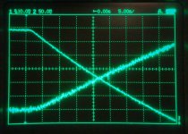
I thought I'd better test my new model, so I measured the rate of temp change of the metal plate compared with the change of diode voltage. Once more the timescale is 5 seconds per large division, temperature 5 degC per large division for both the diode and the LM35 clamped to the plate. A thermal washer Koolpad K230 was fitted between the plate and the LM35.There is no heatsink involved so things get hotter faster. The diode voltage is the trace that starts at the top.
The result is that the diode is responding at about the same time as the external face of the metal plate. This is clearer on some runs I did at 2 seconds per large division. I suspect that in this case the thermal inertia of the LM35 may not be negligible.
Anyway, looks like V2 of my model is also wrong, as it predicts that the diode voltage will significantly lag the plate temp. I'll post the PSPICE output shortly.
(DSC07807 Pic17 sm.JPG)
Attachments
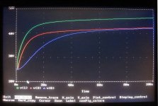
This is the PSPICE output. V(1) is junction temp, V(3) temp of the middle of the copper plate, and V(6) the diode temp.
As you can see, the last significantly lags the plate temp, by a good 15 seconds, which is nothing like what I have just measured in Experiment 2.
Clearly time for model V3, but it's now a puzzler what to do about the impossibly long time constant I found in Experiment 1.
As you can see, the last significantly lags the plate temp, by a good 15 seconds, which is nothing like what I have just measured in Experiment 2.
Clearly time for model V3, but it's now a puzzler what to do about the impossibly long time constant I found in Experiment 1.
Attachments
DouglasSelf said:
Hi Bob
I thought I'd better test my new model, so I measured the rate of temp change of the metal plate compared with the change of diode voltage. Once more the timescale is 5 seconds per large division, temperature 5 degC per large division for both the diode and the LM35 clamped to the plate. A thermal washer Koolpad K230 was fitted between the plate and the LM35.There is no heatsink involved so things get hotter faster. The diode voltage is the trace that starts at the top.
The result is that the diode is responding at about the same time as the external face of the metal plate. This is clearer on some runs I did at 2 seconds per large division. I suspect that in this case the thermal inertia of the LM35 may not be negligible.
Anyway, looks like V2 of my model is also wrong, as it predicts that the diode voltage will significantly lag the plate temp. I'll post the PSPICE output shortly.
(DSC07807 Pic17 sm.JPG)
Hi Doug,
I think this agrees with my observations - that the diode junction temperature does not significantly lag that of the header.
On the subject of the thermal mass of the header/transistor assembly, I should mention that I previously arrived at the estimated thermal mass by a second method as well, I think not unlike what you describe here. I measured the rate of temperature change of the assembly when it was not in contact with a heat sink and observed the "thermal slew rate", where power in was like a current source feeding an integrating capacitor (the thermal mass). The degree of perfectness of the integrator in this arrangement is only limited by the fairly high thermal resistance from case to ambient. By this method, I arrived at a thermal mass on the order of 8 Farads (8 J/C), which was not far off from the 9 F I arrived at by the other technique.
Cheers,
Bob
Stinius has pointed out to me and Bob that there is actually a patent for the ThermalTrak device. You can find it here:
http://www.google.com/patents?id=kU...&as_miny_is=2009&as_maxm_is=1&as_maxy_is=2009
The inventor is given as Mark Busier, the name on the application note that failed to arouse universal enthusiasm. It gives a lot of detail about the internal structure and would have saved us a heap of speculation.
I have to confess that it never occurred to me that such an obvious idea could be patented, especially since the Sanken devices have been around for years. I clearly have lots to learn about the US patent system.
My thanks to Stinius!
DouglasSelf said:Stinius has pointed out to me and Bob that there is actually a patent for the ThermalTrak device. You can find it here:
http://www.google.com/patents?id=kU...&as_miny_is=2009&as_maxm_is=1&as_maxy_is=2009
The inventor is given as Mark Busier, the name on the application note that failed to arouse universal enthusiasm. It gives a lot of detail about the internal structure and would have saved us a heap of speculation.
I have to confess that it never occurred to me that such an obvious idea could be patented, especially since the Sanken devices have been around for years. I clearly have lots to learn about the US patent system.
My thanks to Stinius!
Thank you Douglas
As we discussed on e-mail, you are right, we have a lot to learn about the US patent system.
On my way out office the other day I saw that you had sent me an email, witch I haven’t responded to yet, the same to Bob and John Gedde.
I’m using a laptop now without my email account so I will answer all of you as soon as I’m back at the office.
Have you done the measurements John?
Stinius
DouglasSelf said:Stinius has pointed out to me and Bob that there is actually a patent for the ThermalTrak device. You can find it here:
I have to confess that it never occurred to me that such an obvious idea could be patented, especially since the Sanken devices have been around for years. I clearly have lots to learn about the US patent system.
You presume the Patent Examiner knew about the Sanken device. They are not ALL knowing, and only have a few hours to search for prior art.
- Status
- This old topic is closed. If you want to reopen this topic, contact a moderator using the "Report Post" button.
- Home
- Amplifiers
- Solid State
- On Semi ThermalTrak