I also asked for pricing/payment info. Waiting for a reply.
PCB Group buy, round 2. Please Update the list yourselves when you type:
you can add your name in here please:
1. presbel = 2 pcb ( 4HV shunt + 4 Filament)
2. m461c14n = 1 pcb
3. kstlfido = 2 pcb
4..Sorr = 1 1/2 pcb
i make group second!
Quanghao
PCB Group buy, round 2. Please Update the list yourselves when you type:
you can add your name in here please:
1. presbel = 2 pcb ( 4HV shunt + 4 Filament)
2. m461c14n = 1 pcb
3. kstlfido = 2 pcb
4. Sorr = 1 1/2 pcb
5. ksnider1 = 2 pcb
6. fredlock = 1 pcb
7. pinholer = 1 pcb
you can add your name in here please:
1. presbel = 2 pcb ( 4HV shunt + 4 Filament)
2. m461c14n = 1 pcb
3. kstlfido = 2 pcb
4. Sorr = 1 1/2 pcb
5. ksnider1 = 2 pcb
6. fredlock = 1 pcb
7. pinholer = 1 pcb
PCB Group buy, round 2. Please Update the list yourselves when you type:
you can add your name in here please:
1. presbel = 2 pcb ( 4HV shunt + 4 Filament)
2. m461c14n = 1 pcb
3. kstlfido = 2 pcb
4. Sorr = 1 1/2 pcb
5. ksnider1 = 2 pcb
6. fredlock = 1 pcb
7. pinholer = 1 pcb
8. j45yip = 1 pcb
you can add your name in here please:
1. presbel = 2 pcb ( 4HV shunt + 4 Filament)
2. m461c14n = 1 pcb
3. kstlfido = 2 pcb
4. Sorr = 1 1/2 pcb
5. ksnider1 = 2 pcb
6. fredlock = 1 pcb
7. pinholer = 1 pcb
8. j45yip = 1 pcb
PCB Group buy, round 2. Please Update the list yourselves when you type:
you can add your name in here please:
1. presbel = 2 pcb ( 4HV shunt + 4 Filament)
2. m461c14n = 1 pcb
3. kstlfido = 2 pcb
4. Sorr = 1 1/2 pcb
5. ksnider1 = 2 pcb
6. fredlock = 1 pcb
7. pinholer = 1 pcb
Note
1Pcb have: 2 SSHV + 2 filament!
Originally Posted by pinholer
PCB Group buy, round 2. Please Update the list yourselves when you type:
you can add your name in here please:
1. presbel = 2 pcb ( 4HV shunt + 4 Filament) - already received the PCB
2. m461c14n = 1 pcb
3. kstlfido = 2 pcb
4. Sorr = 1 1/2 pcb
5. ksnider1 = 2 pcb
6. fredlock = 1 pcb
7. pinholer = 1 pcb
I was included in round 1
PCB Group buy, round 2. Please Update the list yourselves when you type:
Note
1Pcb have: 2 SSHV + 2 filament!
you can add your name in here please:
1. m461c14n = 1 pcb
2. kstlfido = 2 pcb
3. Sorr = 1 1/2 pcb
4. ksnider1 = 2 pcb
5. fredlock = 1 pcb
6. pinholer = 1 pcb
7. j45yip = 1 pcb
Note
1Pcb have: 2 SSHV + 2 filament!
you can add your name in here please:
1. m461c14n = 1 pcb
2. kstlfido = 2 pcb
3. Sorr = 1 1/2 pcb
4. ksnider1 = 2 pcb
5. fredlock = 1 pcb
6. pinholer = 1 pcb
7. j45yip = 1 pcb
Now the fun comes
110 mA 390 V with resistor load was OK, but it did not like the soft start of the tube.
D.

Now the fun comes
110 mA 390 V with resistor load was OK, but it did not like the soft start of the tube.
D.
That is 43W. Where did you apply that, on what circuit? Do you have the sinking capacity?
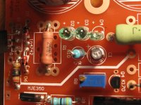
The heatsink is supposed to be 100 W, I applied first to a resistor, managed to adjust the voltage and everything was OK. Then I tried with the amp, but I did not pre-heat the filaments, so I guess that at startup there was no load. Voltage raised and first BUM (I guess the led) then smoke. From what I see R1 and R2 are gone and one of the leds. I suppose that also the semiconductors will not be so happy. What would you unsolder first, to check if they are fried ?
D.
D.
quanghao, Please be involved in the original HV Salas thread as a few hundred boards are being built and we will surely all have issues/questions to be ironed out. Or do you want questions/roadblocks/results handled in this thread?
yes!
The heatsink is supposed to be 100 W, I applied first to a resistor, managed to adjust the voltage and everything was OK. Then I tried with the amp, but I did not pre-heat the filaments, so I guess that at startup there was no load. Voltage raised and first BUM (I guess the led) then smoke. From what I see R1 and R2 are gone and one of the leds. I suppose that also the semiconductors will not be so happy. What would you unsolder first, to check if they are fried ?
D.
Hmm... the destruction shows strong current through Rset (R1), gate stopper (R2) and LEDS. CCS Mosfet and LEDS must have turned to paths then. CCS Mosfet should be checked for sure, and if still a problem occurs, the 2SA1626 (400V MJE350 sub in your 400V application for people to understand). There is a 47R feeding the 100uF LEDS cap. That helps some performance parameter a little, but if you jumper the 47R, and feed the 100uF directly, the LEDS will bias the CCS just one moment faster on startup and that may be critical or not in your experiment. What kind of circuit are you trying to supply, can you describe? Those regs have been used on phono and line applications, an amp feeds B+ through an OPT with large inductance, could be a strong oscillation by driving inductance. I am happy that it could work at 390V 110mA on a dummy, but interfacing to a cct as a load at such voltage and power levels takes some info. Maybe incompatible, or just needed to preheat as you said. Could have shown some behavior when coming up. See first it works on the dummy again. What consumption was that test load resistor creating?
I was surprised that the 100 uF 10V cap did not explode after the diode. If the diode was open there was nothing clamping the voltage below 10 V around it.
I was testing with a 2 20K 25 W resistors in parallel. This was passing around 40 mA in the resistor and 70 mA on the shunt. But I have to admit, I was kind of fast in adjusting the voltage.
I am trying to feed one channel of the Abdellah amp. (Attached)
D.
I was testing with a 2 20K 25 W resistors in parallel. This was passing around 40 mA in the resistor and 70 mA on the shunt. But I have to admit, I was kind of fast in adjusting the voltage.
I am trying to feed one channel of the Abdellah amp. (Attached)
D.
- Status
- This old topic is closed. If you want to reopen this topic, contact a moderator using the "Report Post" button.
- Home
- More Vendors...
- Quanghao Audio Design
- OLD THREAD Simplistic Mosfet HV Shunt (The Simpler Simplistic Design by Salas)