This would be great !! It's also not very clear to me where you have to measure the current, how to set it, and so on.
D.
Its all in the Salas thread, you need to read it and take notes (of course my dumb *** didn't take notes so I have to read it again!)
PCB Group buy, round 2. Please Update the list yourselves when you type:
1. presbel = 2 pcb ( 4HV shunt + 4 Filament)
2. m461c14n = 1 pcb
3. kstlfido = 2 pcb
4. tomes =1 pcb
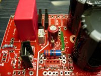
This is a shunt HV PCB Salas.
Sunday this week I will send for your pcb
quanghao
I got the pcb in perfect conditions
but I have question

The pads are not tinned or golded , so were others sources used to protect the pads against the oxidation ???
(pads are cooper coloured)
quanghao
I got the pcb in perfect conditions
but I have question
The pads are not tinned or golded , so were others sources used to protect the pads against the oxidation ???
(pads are cooper coloured)
You probably can tin the pads yourself for extra protection.
Simple question: on the instructions of the board it looks like I am supposed to use a transformer NOT CT, but the board has three connection for transformer wire. I understood that the board include a bridge rectifier. What type of transformer should I use ? How to connect it ?
I saw the questions on the DAC GB, but they are even more confusing.
Thanks,
Davide
I saw the questions on the DAC GB, but they are even more confusing.
Thanks,
Davide
Let us do so ourselves. I've created a WIKI where I'll (and hopefully you all) put info on how to ensure the board works properly.would you be so kind and create a paper with a step by step guid how to
plan the regulator. For example:
Simplistic Mosfet HV Shunt (The Simpler Simplistic Design by Salas) Instructions - diyAudio
Simple question: on the instructions of the board it looks like I am supposed to use a transformer NOT CT, but the board has three connection for transformer wire. I understood that the board include a bridge rectifier. What type of transformer should I use ? How to connect it ?
I saw the questions on the DAC GB, but they are even more confusing.
Thanks,
Davide
Populate only D10 and D12 and you can use a CT transformer. Leave D9 and D11 unpopulated.
If you use bridge rectifiers (for a transformer without CT), populate all D9 - D12, connect the 2 HV leads of the transformer to the 2 AC pads (the CT pad should not be connected!).
Last edited:
Housing, thanks for the reply !
Another question: looking at the instructions, D1 is a 1N383B 150V 5A diode.
Is it correct ? I cannot find this component. Even if I google 1N383B I do not get anything.
5A ? Isn't a bit too much ?
Additionally, I am using the Solen Fastcap 1uF capacitors (630V) is this a good choice ?
Thanks,
Davide
Housing, thanks for the reply !
Another question: looking at the instructions, D1 is a 1N383B 150V 5A diode.
Is it correct ? I cannot find this component. Even if I google 1N383B I do not get anything.
5A ? Isn't a bit too much ?
Additionally, I am using the Solen Fastcap 1uF capacitors (630V) is this a good choice ?
Thanks,
Davide
You're welcome. In fact D1 is a 5 watt zener diode 1N5383B. It's there for protection of the IRF9610.
1n5383b
If you already have the Solen, whether it's good or not so good, there's no harm to use it. The most important thing is to make the shunt regulator work first. Try other caps afterwards to see if they work better or not.
Simple question: on the instructions of the board it looks like I am supposed to use a transformer NOT CT, but the board has three connection for transformer wire. I understood that the board include a bridge rectifier. What type of transformer should I use ? How to connect it ?
I saw the questions on the DAC GB, but they are even more confusing.
Thanks,
Davide
yes you can use CT for the supply. no problem. but need 2 diode!
Thanks,
And I guess D1 is mounted off board, just between the pins of the IRF9610.
In case I cannot find 150 V, can I use two 75 V in series ?
D.
Don't put that there yet because Quanghao reported problems with it in his former layout. Let it work first without it, so you know it does OK, and if you got a spare mosfet in case it kills, put a single 150V 5A one if you find, straight underneath, short legs, with its anode on drain and cathode (stripe) towards source & Rset. If it kills for some reason, change mosfet and forget. Works in my build perfectly, works in two simulators also, but who knows in another layout or with two in series.
Good idea the wiki !
I went through all the thread of the development, and I took some notes of things that can be useful. First thing is a table Current vs value of R1.
My question is: is this universal, or it depends on the voltage that you have on the leds ?
I wanted also to propose a draft for a step by step design and tuning. The goal would be a guide to determine:
A) If you have to use the High or low voltage version.
B) The voltage and current of the transformer in case of CT or not CT.
C) The value of R1.
D) The approx value of R8
E) Determine the heatsink requirements.
..I try, please correct me, when we have a good version we put it on the wiki:
1) Determine operating voltage (Vload) and max load current (Iload).
2) If Vload>300 V
Q2=MPSA94
R3= 82K/5W
R4=220K/2W
If Vload< 300 V
Q2=MJE350
R3=56K/5W
R4=120K/2W
3) Iload+25mA < Iccs < 2 * Iload
Vload + 25 V < Vccs < Vload + 50V
(higher values of Iccs and vccs improve performances, but increase the heat production, I would start with a minimum needed difference between Iload and Iccs and vccs)
4) Make a first estimate of R1 using the following table
Iccs=40mA >>R1=56R/1W
Iccs=50mA >>R1=47R/1W
Iccs=60mA >>R1=33R/1W
Iccs=80mA >>R1=22R/1W
Iccs=100mA >>R1=20R/1W
5) Use PSU2 to determine the AC voltage needed considering the chosen topology of the filter.
6) Set the trimmer R8 to 500 ohm
7) connect as dummy load a 15K/20W resistor (Note: I think this has to be increased in extreme applications)
8) connect two voltmeters, set on DC, one on the dummy load and one on R1.
9) power the circuit
10) with extreme care, and the left hand behind your back, adjust the output voltage to Vload.
11) Note the voltage Vr1 measured on R1 (should be in the range of few volts). The real Iccs can be calculated Iccs=Vr1/R1
Next post the notes on the heat dissipation.
PLEASE NOTE THIS IS A DRAFT, DON'T TAKE IT AS INSTRUCTIONS UNTIL IS NOT CORRECTED !!
Hope this helps,
Davide
- Status
- This old topic is closed. If you want to reopen this topic, contact a moderator using the "Report Post" button.
- Home
- More Vendors...
- Quanghao Audio Design
- OLD THREAD Simplistic Mosfet HV Shunt (The Simpler Simplistic Design by Salas)