ok, I will try this.. What exactly is ment "to a plate-thru' via"?CustomHT,
I don't have the regulator board, I have the HV shunt supply PCBs only.
Don't populate the 4 HV rectifiers and the 4 snubber capacitors on your board. Instead solder the center tap to a plate-thru' via connected to the -ve pole of C5 (100uF/450V) and the rectified HV to a plate-thru' via connected to the +ve pole of C5.
In such case, you can use the full 200mA capacity of the transformer.
Do I simply soldier the leads to the -ve and +ve pole's of C5 as suggested?
Cheers
I read the Dac End 2 webpage, saw where he was experimenting with filters. If you are having trouble with no filter, one option is to increase the miller effect of the tube by adding a small cap from the grid to the plate, its capacitance is multiplied by mu and is a 2nd order low pass filter.
ok, I will try this.. What exactly is ment "to a plate-thru' via"?
Do I simply soldier the leads to the -ve and +ve pole's of C5 as suggested?
Cheers
Yes, you can.
CustomHT,
I don't have the regulator board, I have the HV shunt supply PCBs only.
Don't populate the 4 HV rectifiers and the 4 snubber capacitors on your board. Instead solder the center tap to a plate-thru' via connected to the -ve pole of C5 (100uF/450V) and the rectified HV to a plate-thru' via connected to the +ve pole of C5.
In such case, you can use the full 200mA capacity of the transformer.
CustomHT,
Don't get confuse. What housing meant was you already rectified the ac voltage outside the board and the rectified voltage which is DC is connected directly to the + and - leads of the C5.
I think Apelizzo is using the same transformer as we are, so why not try just the green and orange wire?
Attachments
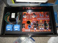
I finally completed the Salas shunt regulator!
I tested with 3 x 9V ac transformer. Is very stable but I can not adjust
less than +/-5.72V for AD1865. R1, R7 = 33R 2W heat! Which should be the maximum voltage?
For CS8414 I managed to adjust minimum 5.28V. R13 = 22R. Is OK?
I tested with 3 x 9V ac transformer. Is very stable but I can not adjust
less than +/-5.72V for AD1865. R1, R7 = 33R 2W heat! Which should be the maximum voltage?
For CS8414 I managed to adjust minimum 5.28V. R13 = 22R. Is OK?
I finally completed the Salas shunt regulator!
I tested with 3 x 9V ac transformer. Is very stable but I can not adjust
less than +/-5.72V for AD1865. R1, R7 = 33R 2W heat! Which should be the maximum voltage?
For CS8414 I managed to adjust minimum 5.28V. R13 = 22R. Is OK?
They should be adjusted to 5.5 - 5.6 volts.
Hi to all,
because i focused to build my own DAC project, i have something to offer:
- Full set of PCB´s (DAC END, Salas Shunt, I/V stage, PSU for I/V stage)
- AD1865 N-K DAC Chip
- CS8414 Receiver Chip
If anyone is interested, please send me a PM.

Parts are sold!
Heatsinks you can find here: TO-220 Heatsink, Small Power Aluminum Heat-Sink, x 4pcs - eBay (item 260481603013 end time Apr-21-10 23:26:12 PDT). Although it says TO-220 its dimensions fit the TO247 package.I manage to found almost all components.
I still have problems with the heatsinks and the caddok resistors. Where did you get these ?
Thanks,
Davide
Last edited:
I manage to found almost all components.
I still have problems with the heatsinks and the caddok resistors. Where did you get these ?
Thanks,
Davide
Caddocks are available at mouser.com. Mouser part no. 684-MK132V-200
Regards,
Frd.
CustomHT,
Don't get confuse. What housing meant was you already rectified the ac voltage outside the board and the rectified voltage which is DC is connected directly to the + and - leads of the C5.
I think Apelizzo is using the same transformer as we are, so why not try just the green and orange wire?
Ok that makes sence. Basically the board is made so I could have just used mains voltage connected straight to the 200-250V connection, but since I am using the output from the trannie I bypass the rectifier section..
I will try connecting the green and orange wire to the + and - wire of C5. And post results..
 Don't connect the green and orange wire directly to C5. It needs to go thru a diode first for rectification and then connect it to C5. If you do this, then wear a safety glass first before you turn on.
 Thanks a lot !! Now all the components are on order.
One question: I am using the PCB for the Salas HV regulator. What value should I use for the current setting resistor R1 ?
Thanks,
Davide
R1= 47R or 56R/2W. You can measure V at R1.
I think I am over project'd right now and would like to sell my boards if someone is interested.
I have the 4 boards, plus the Analog 1865N-K chip from Mikel-Ann's GB. Additionally I have a few caps for the salas board to throw in.
I am looking for a decent offer on this. PM if interested.
I have the 4 boards, plus the Analog 1865N-K chip from Mikel-Ann's GB. Additionally I have a few caps for the salas board to throw in.
I am looking for a decent offer on this. PM if interested.
- Status
- This old topic is closed. If you want to reopen this topic, contact a moderator using the "Report Post" button.
- Home
- More Vendors...
- Quanghao Audio Design
- OLD THREAD DAC End by Andrea Ciuffoli