thanks for the reminder....that means I need a set of 2.2R and 1R and 220 and 200R trimmer for this project....going shopping and broke again...
What is the AC voltage for the heater AC input?
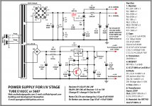
Try to keep the resistors on 2.2R so you help the regulator. I suggest to select LT1085 for regulator and not the LM338.
The multiturn 200R trimpot is standard value and easy to find. 220R is not standard and you cannot find it, but the value here is not critical.
Replace R11 1K with 560R so you can adjust the voltage to 6.3V
So:
1) mount 2.2R resistor
2) mount LT1085
3) mount R11 560R
4) mount 200R trimpot
Do not connect the I/V board with tubes at this stage because if voltage is around 7volts you may destroy the tube.
So load the power supply with three 1.2R 5W resistor in series so you load the power supply like having the tubes connected.
Now adjust the voltage to 6.3V
If relay chattering then replace 2.2R with lower value.
When everything ok do some power cycles and check if relay engages ok. If you have the scope check the ripple on output. You must load as I told you before you check.
After all this you can connect the I/V board (of course you need to adjust the High voltage side to 270V)
I hope it helps.
Last edited:
What is the AC voltage for the heater AC input?
I think i will use 9V since you said it's ok....
Do not connect the I/V board with tubes at this stage because if voltage is around 7volts you may destroy the tube.
So load the power supply with three 1.2R 5W resistor in series so you load the power supply like having the tubes connected.
Now adjust the voltage to 6.3V
If relay chattering then replace 2.2R with lower value.
When everything ok do some power cycles and check if relay engages ok. If you have the scope check the ripple on output. You must load as I told you before you check.
After all this you can connect the I/V board (of course you need to adjust the High voltage side to 270V)
I hope it helps.
You mean load at the heater and B+ section at the output with 3 resistors to adjust the trimpot....????
An externally hosted image should be here but it was not working when we last tested it.
After all this you can connect the I/V board (of course you need to adjust the High voltage side to 270V)
If the voltage slightly exceed to 270v+/-30v after adjusting the R1, R2 & R3 value would this be a no no...???
Last edited:
in this question, im sorry , I do not answer! ( there are on member ask me that)Hi Quanghao.
Cangratulations for the interesting project.
I have some question for you.
1.Is it really necessary to supply pin 18 (M2) to a dedicated regulator(VD4)?
If so, why don't you connect also pin 24 (M1) to VD4 instead of VD3?
I was the one who asked. IMHA it's a waste of part... Just put it to high.
I was the one who asked. IMHA it's a waste of part... Just put it to high.
http://www.diyaudio.com/forums/group-buys/155960-dac-end-andrea-ciuffoli-group-buys-21.html
post 203

Can someone please outline to me what i need to do in order to run 6n6p tubes.
What voltages do i need (my input transformer is 300v, and my heater is 9v (5amp).)
What modifications are needed in order to run these valves, if any.
Thanks
voltage wise, and heater wise the specs are pretty much the same.
However, the 6n6p has a completely different pinout, so you will need to either.... air wire your sockets, or cut traces and reroute using wire to the socket.
An externally hosted image should be here but it was not working when we last tested it.
the pinouts couldnt be much more different... frustratingly.
Last edited:
here is the css load which i'll try soon.
Its a casocode dn2540n5 (upper) and dn2535n3 lower.
I'll adjust the Rset (trimmer) to allow 30ma, so 15ma through each triode. wether the reg will work at this increased load we shall soon find out.
An externally hosted image should be here but it was not working when we last tested it.
Its a casocode dn2540n5 (upper) and dn2535n3 lower.
I'll adjust the Rset (trimmer) to allow 30ma, so 15ma through each triode. wether the reg will work at this increased load we shall soon find out.
1. Strosek: full set
2. boudy : full set
3. ksnider1: full set
4. toufu : (IV + Supply For IV) x 2
5. ferrari: (IV + Supply For IV) x 2
6. analogdiy: full set
7. wobii: full set
8. Cobra2: (IV + Supply For IV) x 2
9. mikelm: full set
Hi all! the next weed i will finis all PCB for 9-15 member !
2. boudy : full set
3. ksnider1: full set
4. toufu : (IV + Supply For IV) x 2
5. ferrari: (IV + Supply For IV) x 2
6. analogdiy: full set
7. wobii: full set
8. Cobra2: (IV + Supply For IV) x 2
9. mikelm: full set
Hi all! the next weed i will finis all PCB for 9-15 member !
I think i will use 9V since you said it's ok....
You mean load at the heater and B+ section at the output with 3 resistors to adjust the trimpot....????
An externally hosted image should be here but it was not working when we last tested it.
If the voltage slightly exceed to 270v+/-30v after adjusting the R1, R2 & R3 value would this be a no no...???
My mistake...perhaps this is the right way to load the heater to adjust the voltage to 6.3V....3 resistors in series....please correct me if i'm wrong...
An externally hosted image should be here but it was not working when we last tested it.
My mistake...perhaps this is the right way to load the heater to adjust the voltage to 6.3V....3 resistors in series....please correct me if i'm wrong...
An externally hosted image should be here but it was not working when we last tested it.
Yes, That's is how I did.
Yes, That's is how I did.
Thanks...did your the psu working fine ?
Thanks...did your the psu working fine ?
Yes, I replaced R11 with 680r and R8/R9 with 1r. Then there where no problem adjusting to 6.3V...
I haven't still managed to get full voltage from the HV section. I have followed the steps suggested in this thread and got aprox. 260V. As soon as possible I will try and fiddle some more with it.
1. Strosek: full set
2. boudy : full set
3. ksnider1: full set
4. toufu : (IV + Supply For IV) x 2
5. ferrari: (IV + Supply For IV) x 2
6. analogdiy: full set
7. wobii: full set
8. Cobra2: (IV + Supply For IV) x 2
9. mikelm: full set
10. le´flu: just one salas reg please
Hi all! the next weed i will finis all PCB for 9-15 member !
Thanks...did your the psu working fine ?
Hi gabanyayaya!
I fix it in the circuit! Thank you
Attachments
Hi gabanyayaya!
I fix it in the circuit! Thank you
Hi,
I would also delete LM338 from schematic to avoid complications and leave LT1084 or LT1085 so you have only to play with R8 and R9
1. Strosek: full set
2. boudy : full set
3. ksnider1: full set
4. toufu : (IV + Supply For IV) x 2
5. ferrari: (IV + Supply For IV) x 2
6. analogdiy: full set
7. wobii: full set
8. Cobra2: (IV + Supply For IV) x 2
9. mikelm: full set
10. le´flu: just one salas reg please
11. jasujonas: full set
2. boudy : full set
3. ksnider1: full set
4. toufu : (IV + Supply For IV) x 2
5. ferrari: (IV + Supply For IV) x 2
6. analogdiy: full set
7. wobii: full set
8. Cobra2: (IV + Supply For IV) x 2
9. mikelm: full set
10. le´flu: just one salas reg please
11. jasujonas: full set
- Status
- This old topic is closed. If you want to reopen this topic, contact a moderator using the "Report Post" button.
- Home
- More Vendors...
- Quanghao Audio Design
- OLD THREAD DAC End by Andrea Ciuffoli