Hi Luka, the maximum current that your power supply can give is limited by the saturation current
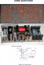
of your output choke. If your choke saturates the current in the primary will rise too quickly leading to mosfet destruction. Why don't you try to put a current transformer in series with the 2.2uf cap to sense the primary current? You can use a small high permeability toroid with 100 turns and just pass the wire connecting the 2.2uf cap to the trafo trough it. Rectify the secondary of the current trnsformer with 4 diodes and convert the current in voltage with a resistor. Throw that voltage into a fast comparator and use it to disable the ir2110 (much faster than the sd pin of the 3525). You have just to be sure to set the current limit point lower than the point where your output choke saturates. If you do the things well you can make it short circuit protected.
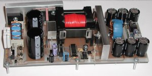
Btw: which core have you used for the output choke? It seems quite small for 100uH at a reasonable current.
Another thing I notice on the layout is the too small safety distance between primary and secondary. Keep the distance at least the same as the optocoupler pitch.
It is not my intention to criticize your design I just give you suggestions on how to make it better and more stable.
Ciao
-marco
of your output choke. If your choke saturates the current in the primary will rise too quickly leading to mosfet destruction. Why don't you try to put a current transformer in series with the 2.2uf cap to sense the primary current? You can use a small high permeability toroid with 100 turns and just pass the wire connecting the 2.2uf cap to the trafo trough it. Rectify the secondary of the current trnsformer with 4 diodes and convert the current in voltage with a resistor. Throw that voltage into a fast comparator and use it to disable the ir2110 (much faster than the sd pin of the 3525). You have just to be sure to set the current limit point lower than the point where your output choke saturates. If you do the things well you can make it short circuit protected.
Btw: which core have you used for the output choke? It seems quite small for 100uH at a reasonable current.
Another thing I notice on the layout is the too small safety distance between primary and secondary. Keep the distance at least the same as the optocoupler pitch.
It is not my intention to criticize your design I just give you suggestions on how to make it better and more stable.
Ciao
-marco
Yes yes and yesHi Luka, the maximum current that your power supply can give is limited by the saturation current
of your output choke. If your choke saturates the current in the primary will rise too quickly leading to mosfet destruction. Why don't you try to put a current transformer in series with the 2.2uf cap to sense the primary current? You can use a small high permeability toroid with 100 turns and just pass the wire connecting the 2.2uf cap to the trafo trough it. Rectify the secondary of the current trnsformer with 4 diodes and convert the current in voltage with a resistor. Throw that voltage into a fast comparator and use it to disable the ir2110 (much faster than the sd pin of the 3525). You have just to be sure to set the current limit point lower than the point where your output choke saturates. If you do the things well you can make it short circuit protected.
Btw: which core have you used for the output choke? It seems quite small for 100uH at a reasonable current.
Another thing I notice on the layout is the too small safety distance between primary and secondary. Keep the distance at least the same as the optocoupler pitch.
It is not my intention to criticize your design I just give you suggestions on how to make it better and more stable.
Ciao
-marco
Since I would only need it for high peak power of music, and pretty low average overall, I need only fuses.
I am not sure anymore of what value did I measure it (unless I wrote it here), core if out of PC supply
About safety I know from the very start, even Eva warned me as did you, still noted... for this one is as it is, there will come time, that I will redo it all
In fact I don't even think you see my current state of supply, sure is not the same output inductor as in picture above
I guess I will need to take picture and post it
You are right your average power will be low but what happens if your multi kw classD amp connected to it fail in short between +B and -B? The fuses blows but you will have a peak current in the primary that can reach tens of amperes if the choke saturates and lose its inductance. A mosfet will blow much quicker than a fuse....
If you grab your choke from a pc it is quite surely a micrometals material 26, its saturation is quite soft and thus its allows you to have huge peak currents without loosing too much inductance.
Can you show me some pictures of the actual status of the smps; it seems simple but really well done.
If you grab your choke from a pc it is quite surely a micrometals material 26, its saturation is quite soft and thus its allows you to have huge peak currents without loosing too much inductance.
Can you show me some pictures of the actual status of the smps; it seems simple but really well done.
i meant the values of the components . thanks luka
For that you have schematic, which you can download, values of elements, you will find therei meant the values of the components . thanks luka
For that you have schematic, which you can download, values of elements, you will find there
sorry for disturbing but there are some components values which are not visible . pls send me a black and white pdf of components my email is stevekamala@yahoo.com
thanking you in advance steve
I've read through all 110 pages of this thread. The least I can say is THANKS, THANKS AND THANKS Luka for sharing your designs and following up on the thread long after you got your smps working.
Thanks Chas1 for your support in the maze of calculatons and sharing your desings,especially transformer gate drive.
Thanks Eva for your extensive knowledge in smps that you shared with us.
Thanks to everyone who posted on this thread and contributed to this topic.
I cannot forget to thank my countryman Stewin who adviced me to look up this thread. I've gained a lot of knowledge in half bridge smps and i hope I'll build one myself (with your help of course!).
I still have questions though, I'll just do some more reading before I start putting things together. I already have enough components for the whole circuit, I'll just have to buy the pwm chip.
There was a mention of Chas1's website,does anyone know the url?
I'll post my requirements some other time after I assemble the controll circuit.
Regards,Xeclipse.
wau, all 110 pages?? to bad not all were good, but I think you can see how you can start from not knowing anything, to having something you can use. Sincemy friend I and back in the day didn't have this info, we started on this, while I posted.
But I feel it is time for new design, redo everything, use what was learned and make it even more simple! This will take some time, as we get older we have less and less time for such things, but...
Also, I am not aware that chas had or has any website, in case I am wrong, I'll let him tell us
But I feel it is time for new design, redo everything, use what was learned and make it even more simple! This will take some time, as we get older we have less and less time for such things, but...
Also, I am not aware that chas had or has any website, in case I am wrong, I'll let him tell us
All 110 pages! It took me several days,i finished reading this morning.
I learnt a lot of stuff,i dint even knew the difference between HB and FB! I also found an online turns calculator.
I still have some questions:
Can bjt's work to a fsw of 100khz? If yes,is there any changes in gate/base drive?
Incase of unregulated supply, is an inductor necessary? What about the % overwind in the secondary?
I dont know if this is 'too wrong', but i tend to think that an optocoupler is not necessary in the fb loop since the pwm chip and the outputs are both in the secondary of the smps.
There was a mention of Chas1's 'project', maybe i mistook it for a website.
Regards,Xeclipse.
- Home
- Amplifiers
- Power Supplies
- Offline full-bridge SMPS… need help