Sniff around for the M2Clone PCB sold by member "Tea-Bag" and read that thread. If I'm recalling correctly, several people built an M2 without mu-metal shielding, and loved the way the amp sounded. Several other people did make their own mu-metal shield, and they also loved the way the amp sounded. Search this thread, and that thread, for photos. I'll bet you find more than one picture of a homemade mu-metal shield on an M2 amplifier board.
Remember that M2 has excellent PSRR.
....
Of course that's EXACTLY why I did it

Actually I hadn't thought of that at all - good point

I just happen to find that good SMPS is quieter than a linear PSU that isn't 100% ideal...Especially with my mains. I must be deaf, because I don't hear the terrible noise everyone grumbles about.
I do plan on scoping this 'thing' with the current meager capacitance, and later when I add more. I'll turn to better experts than I; as what to look for.
An SMPS is very different than a rectifier+capacitor linear supply.
A rectifier+capacitor linear supply has lots of 2*fmains ripple (>1000 mV is typical) and very little HF noise.
An SMPS has zero 2*fmains ripple, and lots of HF noise (100mV is typical)
Those are not the same.
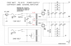
Thus it may be true, wink wink, that the partitioning of a CRC supply ripple filter as found in Nelson Pass's M2 supply (attached below), has a VERY different optimum point for a rectifier+capacitor linear supply, than for an SMPS. The optima may be VERY different.
Fool with it in simulation. Fool with it on the lab bench. Find out what your test instruments tell you. Listen to the equipment and find out what your ears tell you. Best for SMPS may be very different than best for rectifier+capacitor linear supply.
A rectifier+capacitor linear supply has lots of 2*fmains ripple (>1000 mV is typical) and very little HF noise.
An SMPS has zero 2*fmains ripple, and lots of HF noise (100mV is typical)
Those are not the same.
Thus it may be true, wink wink, that the partitioning of a CRC supply ripple filter as found in Nelson Pass's M2 supply (attached below), has a VERY different optimum point for a rectifier+capacitor linear supply, than for an SMPS. The optima may be VERY different.
Fool with it in simulation. Fool with it on the lab bench. Find out what your test instruments tell you. Listen to the equipment and find out what your ears tell you. Best for SMPS may be very different than best for rectifier+capacitor linear supply.
Attachments
Of course that's EXACTLY why I did it
Actually I hadn't thought of that at all - good point
I just happen to find that good SMPS is quieter than a linear PSU that isn't 100% ideal...Especially with my mains. I must be deaf, because I don't hear the terrible noise everyone grumbles about.
I do plan on scoping this 'thing' with the current meager capacitance, and later when I add more. I'll turn to better experts than I; as what to look for.
Here was my saga with linear vs smps on m2.
Strange Forest of Noise with Linear PSU
Haha, maybe it's Tea Bag that I need to get the money back from? In all seriousness, it's not the amp's fault - it is the nature of toroidal transformer linear PSU's. It is like you said, the ripple at line freq, 2f, 3f, 4f, etc is huge and it's all in the audible "hum" band. Whereas, a SMPS is at 400kHz, well above audible and easy to filter out with a steep low pass filter for the audible range. Linear supplies, are connecting your audio to a 120vrms noise source (that's 340vpp) that is in-band with your audio signal. Despite all the filtering that a CRC can do, there is still quite a large amount of ripple left over.
Oh good, he's here.....
Mr. Pass, can I get my money back?
All kidding aside - many thanks for sharing a wonderful circuit
Apologies - I had no intention to invoke the (possibly) never ending SMPS debate. Just that the M2 seems to be working for me well as such - I can't put a loaded toroid on my lines without being mistaken for a beekeeper.
When I am complete with the thing, and have some time - I want to open a thread to see how this looks on some test equip. I have a real FFT receiver that can do 6Khz to 6Ghz, and a 150Mhz scope. With your help, maybe we can get a good idea.
Please continue with the regularly scheduled program.
That would be interesting to see. If possible, tested at both the psu and the amp outputs. I measure some 30mV with a cheap dmm on my stock F6 psu, but nothing on the speaker outputs, but I can pick up 60/120hz and harmonics up to above 2kHz in an FFT with REW, so I am curious how much of that actually comes from the PSU.
Help pls on how to implement separate PSU box for M2
Hey All,
Just beginning to put together my M2C build using Teabag's amp and psu boards. I have decided to build as dual mono with psu in a separate box.
I need some help with where best to place rectification and reservoir caps - in the psu or amplifier? I had reasoned that one could place these in the amplifier, with the transformers in a separate box, and thus feed low voltage/high current AC to the amplifier, recognizing that the cables will have to accommodate higher current than mains AC, so larger conductors, and they could pick up all sorts of EM trash between boxes (perhaps not significant), plus the potential for inductance in the cable.
Then I came across this wonderfully detailed not by member Propitious in #2279:
In my ignorance, what are the penalties introducing low voltage AC (18V) versus rectified DC (~24V DC) into the amplifier?
Thanks,
-Keith-
Hey All,
Just beginning to put together my M2C build using Teabag's amp and psu boards. I have decided to build as dual mono with psu in a separate box.
I need some help with where best to place rectification and reservoir caps - in the psu or amplifier? I had reasoned that one could place these in the amplifier, with the transformers in a separate box, and thus feed low voltage/high current AC to the amplifier, recognizing that the cables will have to accommodate higher current than mains AC, so larger conductors, and they could pick up all sorts of EM trash between boxes (perhaps not significant), plus the potential for inductance in the cable.
Then I came across this wonderfully detailed not by member Propitious in #2279:
Attila: You want the rectifier and some caps in the PS so as not to introduce any low voltage AC in the amp. That is the main reason to do it.
In my ignorance, what are the penalties introducing low voltage AC (18V) versus rectified DC (~24V DC) into the amplifier?
Thanks,
-Keith-
(i) Mains frequency AC is the source of mains frequency hum; bringing it near audio circuits introduces the possibility of injecting hum into audio signal paths. Either by magnetic coupling or by electrostatic coupling (or both).
(ii) Bringing AC into the audio chassis means bringing the rectifier diode(s) into the audio chassis. Many people are fearful of diodes, viewing them as virulent sprayers of nasty RF emission. They strongly feel that if you can move the diodes completely out of the audio chassis, why on earth not?
(iii) Locating the transformer in one chassis and the rectifiers in another chassis means you have an extremely long current loop between transformer secondary and rectifiers (meters long rather than centimeters long). Unless you carefully implement critical damping (zeta=1.0) of this distributed RLC circuit, the current loop will carry bursts of high amplitude oscillatory ringing, each time the rectifiers turn off: two bursts per mains cycle. The current loop will act as an antenna to broadcast these oscillations into both chassis and into nearby equipment, which is highly undesirable. BTW you achieve critical damping by making a series of lab measurements upon your particular transformer and your particular umbilical cable. Not calculations. Not consultation with experts. Measurements upon your hardware assembly.
Mark: Thank you for explaining in a very detailed way.
To anyone else: please read my full post #2279 and post #801 in "Aleph J illustrated build guide" thread, which has pics. I made those posts mainly to help several people who want to have a separate power supply but have questions how. I show one way that is simple and worked. Anyone is welcome to do another way if it helps them sleep at night. An important point is to try to have large conductors of Ground back to the PS. Zen Mod has said that many times. At a reasonable cost, I used CL-2 four 12 AWG conductor speaker cable for umbilical. It has a slight twist and return wire (Gnd) is next to power wire. If you can get four 10 AWG cable - probably even better. Having some caps near the Amp pcb help nullify the small amount of R and L in the umbilical. Note that for the Aleph J ps, I did overkill with the amount of caps. Lately, I have noticed just as quiet a ps (low ripple) by using a cap multiplier, like juma shows on his Cubie3 thread, which costs less and takes up less space, but that is a conversation for another time and place. If you are a newbie, just go for what you can do, maybe like I did in post #801, and change something if you want to experiment, and then measure and listen to your results, and have fun. That is what this is about.
To anyone else: please read my full post #2279 and post #801 in "Aleph J illustrated build guide" thread, which has pics. I made those posts mainly to help several people who want to have a separate power supply but have questions how. I show one way that is simple and worked. Anyone is welcome to do another way if it helps them sleep at night. An important point is to try to have large conductors of Ground back to the PS. Zen Mod has said that many times. At a reasonable cost, I used CL-2 four 12 AWG conductor speaker cable for umbilical. It has a slight twist and return wire (Gnd) is next to power wire. If you can get four 10 AWG cable - probably even better. Having some caps near the Amp pcb help nullify the small amount of R and L in the umbilical. Note that for the Aleph J ps, I did overkill with the amount of caps. Lately, I have noticed just as quiet a ps (low ripple) by using a cap multiplier, like juma shows on his Cubie3 thread, which costs less and takes up less space, but that is a conversation for another time and place. If you are a newbie, just go for what you can do, maybe like I did in post #801, and change something if you want to experiment, and then measure and listen to your results, and have fun. That is what this is about.
Gentlepeople,
Thanks for your quick and detailed responses - these forums and the people in them are a treasure.
For perspective, the reason I want to put the psu separately is that these transformers (2 x 500VA Primrose toroids) will also be driving a pair of BA-3 monoblocks sometime later this year. Given the cost of power supply hardware, building a common psu for either amplifier seems worthwhile, even though it is rather over-spec'ed for the M2.
Presumably one would also include the cable between the transformer secondary and Quasimodo's input when measuring? Or am I being too simple minded?
I fully agree with your comments on ground wiring, as the ground conductors must hang around long enough for a fuse to blow or to send the fault current back to the circuit breaker. Daunting given the potential magnitude of fault currents...
Thanks for your quick and detailed responses - these forums and the people in them are a treasure.
For perspective, the reason I want to put the psu separately is that these transformers (2 x 500VA Primrose toroids) will also be driving a pair of BA-3 monoblocks sometime later this year. Given the cost of power supply hardware, building a common psu for either amplifier seems worthwhile, even though it is rather over-spec'ed for the M2.
Yes, it certainly is. What I was wondering though (and didn't illustrate well) was whether there is a difference between low voltage AC (in the original quote) and high voltage AC? From what I remember of my university physics labs, the coupled electrical and magnetic fields may have a larger radius around the conductor(s) for higher voltages. Perhaps some shielding (such as done by Mighty ZM in his "Papa's Koan (M)2") and scrupulous attention to grounding and wire routing can help with this.(i) Mains frequency AC is the source of mains frequency hum...
Yeah, I think that I can respect both approaches. At the moment, my view is that amidst the forest of EM and magnetic emissions in a typical amplifier case, well-positioned diodes (i.e. not right next to the output transistors) may not hurt performance too much. I guess I'll find out.(ii) Bringing AC into the audio chassis means bringing the rectifier diode(s) into the audio chassis. Many people are fearful of diodes, viewing them as virulent sprayers of nasty RF emission. They strongly feel that if you can move the diodes completely out of the audio chassis, why on earth not?
Ahh, now this is a gem to reflect on. So, could one use your Quasimodo jig to measure the proper snubber arrangement? (I pre-emptively bought a Quasimodo kit, but sadly I am lacking an oscilloscope at the moment...).(iii) Locating the transformer in one chassis and the rectifiers in another chassis means you have an extremely long current loop between transformer secondary and rectifiers (meters long rather than centimeters long)... ...Measurements upon your hardware assembly.
Presumably one would also include the cable between the transformer secondary and Quasimodo's input when measuring? Or am I being too simple minded?
Thanks, I haven't yet read the Aleph J entry, but I will.Mark: Thank you for explaining in a very detailed way.
To anyone else: please read my full post #2279 and post #801 in "Aleph J illustrated build guide" thread, which has pics.
I fully agree with your comments on ground wiring, as the ground conductors must hang around long enough for a fuse to blow or to send the fault current back to the circuit breaker. Daunting given the potential magnitude of fault currents...
I will, and thanks again for your guidance.If you are a newbie, just go for what you can do, maybe like I did in post #801, and change something if you want to experiment, and then measure and listen to your results, and have fun. That is what this is about.
This week I have finished my M2 build. I have started allready with an F6 but have postponed the F6 because I have read meanwhile many times that M2 is the favoured by many DIYers. To be honest a few month ago I was not aware that there are any other First Watt designs than F1-F7
As usual the assembling into chassis, wiring etc. is most of the work but least fun. Therefor I can highly suggest the Disspipante Deluxe 4U Chassis, the pre drilled heat sinks and the plattform makes the built as simple as possible. Unfortunatley I had problems with pre-drilled holes in one of the heatsinks. They did not accept much thread and I had to do some rework. Also resoldering was required to adjust the offset. Had to increase R7 from 47K to 51K (Teabag M2 clone boards with Harris IRFP9240)
First listening was dissapointing. Got slight humming from speakers (88db efficiency) wich could be heard in 3 meter distance in a quite environment. Also the sound was not as smooth as you would expect from a ClassA amplifier.
Hmm, the M2 is noisier (500uV) than other First Watt amplifiers but other builders are using M2 with high efficiency speakers and have not such problems. Means it looks like I did something wrong with my build. After thinking about I found my very stupid mistake. To improve wiring I have overdone star grounding respectively set star ground wrong in my CLC power supply. Find details attached. Shame but lessons learned.
After the rework of wiring it is the quitest (concerning hum) amplifier I have built yet.
Absolutely no hum/noise from speakers. Also the Toroidy transformer is absolutely quite. No humming from transformer itself, you cannot hear any difference if powered or not.
I found out that my ebay relay volume control is worsening the sound, the M2 magic dissapears. A stepped attenuator brings the magic back. Have to check if it is an impedance issue or mains noise related. Have ordered some shorter RCA cables (for connection between stepped attenuator and M2) to improve further.
Will post some pics later and listening impressions as soon the shorter cables arrives.
Thanks to Nelson Pass for sharing his knowledge and excellent circuit designs, teabag, ZM, 6L6, diyAudio store and others for all the usefull hints and work.
As usual the assembling into chassis, wiring etc. is most of the work but least fun. Therefor I can highly suggest the Disspipante Deluxe 4U Chassis, the pre drilled heat sinks and the plattform makes the built as simple as possible. Unfortunatley I had problems with pre-drilled holes in one of the heatsinks. They did not accept much thread and I had to do some rework. Also resoldering was required to adjust the offset. Had to increase R7 from 47K to 51K (Teabag M2 clone boards with Harris IRFP9240)
First listening was dissapointing. Got slight humming from speakers (88db efficiency) wich could be heard in 3 meter distance in a quite environment. Also the sound was not as smooth as you would expect from a ClassA amplifier.
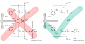
Hmm, the M2 is noisier (500uV) than other First Watt amplifiers but other builders are using M2 with high efficiency speakers and have not such problems. Means it looks like I did something wrong with my build. After thinking about I found my very stupid mistake. To improve wiring I have overdone star grounding respectively set star ground wrong in my CLC power supply. Find details attached. Shame but lessons learned.
After the rework of wiring it is the quitest (concerning hum) amplifier I have built yet.
Absolutely no hum/noise from speakers. Also the Toroidy transformer is absolutely quite. No humming from transformer itself, you cannot hear any difference if powered or not.
I found out that my ebay relay volume control is worsening the sound, the M2 magic dissapears. A stepped attenuator brings the magic back. Have to check if it is an impedance issue or mains noise related. Have ordered some shorter RCA cables (for connection between stepped attenuator and M2) to improve further.
Will post some pics later and listening impressions as soon the shorter cables arrives.
Thanks to Nelson Pass for sharing his knowledge and excellent circuit designs, teabag, ZM, 6L6, diyAudio store and others for all the usefull hints and work.
Attachments
Last edited:
After thinking about I found my very stupid mistake. To improve wiring I have overdone star grounding respectively set star ground wrong in my CLC power supply.
I'm really surprised that star ground wiring can make such a big difference. Maybe pictures of the incorrect and correct ground wire routing will help clear it up for me.
I'll soon be building an M2 as well (Tea-bag's boards & Harris 9240), so want to make sure I don't make the same mistake.
.
- Home
- Amplifiers
- Pass Labs
- Official M2 schematic