Oh, sorry. Yes it was the turntable that had the pop on shutdown.
Well, thanks but it occurred to me that if turntable switching made the sound, putting it on the amp switch wouldnt have any effect, I just failed to think my question through.
Russellc
Like this example
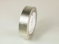
I have Mu metal for this, but I like Soundhappy's suggestion to ALSO use copper tape. Looking at Edcor's site, many of their transformers come in a shielded version. Poking around, they fully describe the material they use, which is a purpose-made solderable tin plated copper from 3M:
EDCOR - Copper Shielding
Lots of places carry the 3M Embossed Tin-plated Copper EMI Shielding Tape 1345 in various widths and lengths. Not cheap for the continuous rolls, but I think I'm going to try it.
BK
Attachments
I WILL use the Mu metal. The 3M tape is extra/easy and routinely employed by Edcor. Belt and suspenders approach, and reversible if it creates a problem.
Can you share your construction method for the shielding box? It looks really great. Sheet metal is a new medium for me.
BK
Can you share your construction method for the shielding box? It looks really great. Sheet metal is a new medium for me.
BK
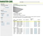
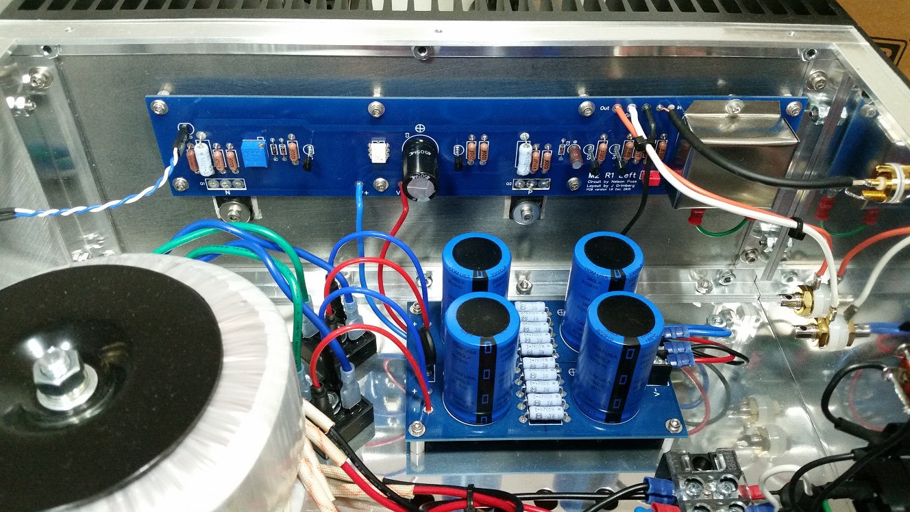
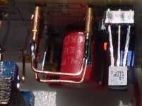
The shiny box at the rightmost end of the PCB is made of 0.010" Mu-Metal, purchased from McMaster-Carr. Why not use the material you already have?
Can you share your construction method for the shielding box? It looks really great.
+1
I traced the flat box on the mu-metal sheet using a thin-tipped Sharpie. I cut the metal using metal snips. I then folded it using a piece of scrap 1/2" square aluminum profile. With a hammer and the scrap aluminum, I made the corners on the sides square. I decided to leave the top corners slightly rounded, but you can use the hammer and scrap to make them square also.
Nice result, grimberg.
Thank you! Back in February I posted other pictures of the build. You can see them at: http://www.diyaudio.com/forums/pass-labs/281520-official-m2-schematic-72.html#post4975080
Looks great. So does the mu metal box have to be grounded? And does it work?
Yes, it has to be grounded. In the picture you can see a short piece of green wire below the mu-metal box. It connects the box to the nearest screw holding the PCB to the standoff. And yes, the shield does work.
for 6: nuttin' - just toss them in without source resistors
for 10: nuttin' - just toss them in with , say, 15R source resistors
Change to 6 mA Idss matched LSK | LSJ buffer jfets without 10R's.
Get resistors is more critical in front end gain stage but less in buffer ?
Councils thoughts about eventual parameters of the buffer to take care
and his source resistors influence?
Attachments


Yes, it has to be grounded. In the picture you can see a short piece of green wire below the mu-metal box. It connects the box to the nearest screw holding the PCB to the standoff. And yes, the shield does work.
I didn't ground mine (which was made of copper) but it still works. That's not to say it wouldn't work better if I grounded it though.
Copper will act like a Faraday cage (electric field shielding), but it won't shield anything from a magnetic field.
Copper has a permeability roughly the same as air (~1). Steels are in the hundreds (some getting up to a thousand or so). Mu-metal is in the 10s of thousands.
Grounding will drain off the charge on the surface of a Faraday cage, but the inner and outer surfaces will have opposite charges making them cancel inside the cage anyway. I don't think grounding does anything at all for magnetic shielding.
Cheers,
Jeff.
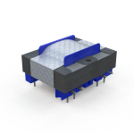
Antek 400 VA toroids are cool for M2 psu
beacause have magnetic shield incorporated.
http://www.antekinc.com/content/AS-4218.pdf
")
beacause have magnetic shield incorporated.
http://www.antekinc.com/content/AS-4218.pdf
Absolutely: mitigate at the source with power transformer design/shielding, don't oversize the transformer VA beyond reason, rotate the transformer to find the minimum lobe, maximize layout distance and/or separate enclosure....then worry about the little Edcor with copper flux bands and/or Mu metal enclosure.
BK
BK
Copper will act like a Faraday cage (electric field shielding), but it won't shield anything from a magnetic field.
Copper has a permeability roughly the same as air (~1). Steels are in the hundreds (some getting up to a thousand or so). Mu-metal is in the 10s of thousands.
Grounding will drain off the charge on the surface of a Faraday cage, but the inner and outer surfaces will have opposite charges making them cancel inside the cage anyway. I don't think grounding does anything at all for magnetic shielding.
Cheers,
Jeff.
Perhaps I should say instead "my amp is quiet", which may or may not be thanks to my nifty little copper boxes.
- Home
- Amplifiers
- Pass Labs
- Official M2 schematic