...... the downside is that all windings MUST have exactly the specified number of turns or else a shorted turn is caused....
Eric.
That is simply incorrect
I said parallel....twice.My guess is that the primary sections are series connected, not parallel.
Last edited:
Ask Brian Sowter about it.....noddies in the standard production area got it wrong first attempts.
Eric.
No, I will not trouble Brian with foolish questions.
Maybe something else was going on.
I said parallel....twice.
So you had a transformer with two parallelled primary sections, and one (or two) secondaries?
Brian must have scratched his head.....
Ask Brian Sowter about it.....noddies in the standard production area got it wrong first attempts.
Eric.
noddies means eeediyots.
Last edited:
"Fine up to 100KHz, this is top limit of my sine-wave generator with low output impedance. I don't think it makes any sense to test above 100 KHz."
For global feedback to work, the more OT bandwidth the better. The resonance freq. of the OT will produce a two pole phase response near it which causes loop instability. The transformer must also be tested with similar source and load impedances to the way it will be used. Just take a look at the Antek toroid OTs to see that, the graphs show what looks like adequate bandpass (probably measured with a low Z signal gen.) but in a real test setup, they only work to 6 KHz (most likely random wound power designs).
SS designs typically use around a 3 MHz loop bandpass, in tube land we are lucky to get 100 KHz in the best OTs. A Hammond OT only specs to 30 KHz, and an Edcor OT only specs to 20 KHz with resonances as low as 30 KHz. These are essentially audio band only OTs. Totally unacceptable for global fdbk. The reason global fdbk has gotten a bad name is so few know what they are doing, and so few do any measurements of the OTs they use. Subjective listening results only have been a disaster. Without testing or data specs, the most common OTs have degraded to pure JUNK status, only suitable for guitar amps.
One is forced to use local feedback schemes to get any kind of decent results with these "low cost" OTs. There are some other techniques to get around the problem, such as the auxilliary HF OT mentioned in RDH4. Never see them used though.
Last edited:
@smoking amp
I did a test wind of a 8k to 4/8 ohms toroid (actually, it's more like 3/7 ohms, those that have experimented with multitap secondaries will immediately know why). Using a 4 quarter primary construction, so primary = a+b+c+d windings, where a+c and b+d were bifilary wound, each bifilary winding in one progressive layer and the secondary winding was placed inbetween - the obvious error was bifilary winding the primary sections and the interwinding capacitance ended up being quite horrible, tens of nF. The transformer is specced for 30W at 16Hz so as you can immagine a lot of iron (think equivalent to 180VA 50Hz mains core dimensions), and relatively less copper. It was wound very nicely, no gaps, no bunching. The resonant frequency was about 50kHz and the -3dB points were around 3Hz on the lower end, and around 45k on the upper end, estimated, because of the resonance peak. Between 20Hz and 20kHz it was within 0.2dB! The figures are indicative but not entirely accurate as it was tested 'backwards' current driven from the secondary, with the primary loaded with 8k. It was also tested in a real amplifier which is pentode mode with Schade feedback so it does not have extremely high output impedance.
Apart from the obvious error (caused by t he winder misinterpreting the balanced DCR requirement), they used wire diameters for a standard mains 30VA toroid so the winding DCR ended up very high because they forgot to figure for the vastly increased wire length due to the larger core.
This example should give you a good enough idea how far you can go when things are done properly.
That being said, the amp that was used to test the transformers was constructed with a toroid OPT in mind. Specifically, this means including both static (bias) and dynamic (drive) balance control for the output stage.
Please note that what I wrote about construction of a toroid OPT is really a very simplified explanation, there are a lot of tricks to it, especially when you get into interstages or isolation transformers which are small, and quite difficult to wind with all those layers and spacers and tapes. I freely admit I'm quite new at this and have done only a few experimental toroid designs (as i write this, I am waiting for the first 'real' OPT to be wound), but it is obvious to me that it holds great potential.
I have done a few calculations and assisted in winding several classic OPTs and doing a toroid requires some new tricks but on the whole, it's FAR less labor intensive, or, should I say, you can get really good results with a lot less effort in front of the winder. Of course, if you start talking an 'all stops pulled' toroid design, then it gets complicated.
@pieter,
i think mrfeedback's mention of a shorted turn effect refers to parallel connecting windings that have an unequal number of turns - as you know, you get a 'distributed' high DCR shorted winding effect by virtue of the currents circulating between the two paralleled windings.
Measuring bandwidth of a tube output transformer with a 5 ohm source does not make sense at all; my two cents that you know this.
Bad, mediocre and top quality transformers differ in HF resonance behavior; optimizing this for a particular application will not give a better measurement but also a better sounding transformer. This has nothing to do with not being able to hear 100 kHz (and another two cents that you know).
My $0.02 for (almost) everything above.
Generator with 5 Ohm output impedance will work just fine with transformer's 5K primary impedance (secondary loaded with 8 Ohm resistor). I have tested output transformer with resonant frequency 40KHz with 2 different generators, with and without resistor simulating Rp, and frequency curve/resonant frequency were very very close. Resonant frequency depends upon leakage inductance and distributed capacitance.
f = 1 / (2 * pi * sqrt (Ls * Cd))
Resistor in series with primary will not change much in this kind of setup, it will not make anything right or wrong.
BTW, any tests with generator are very approximate anyway. Most generators are capable only of 10V output, with ratio 25:1, 8 Ohm load it means 0.4V on secondary (0.02W). Not actual listening level indeed. As experiments show, distributed capacitance changes upon drive level (resembling inverted permeability curve), so real measurements must be made in finished amplifier circuit, with output power >=1 W (miles above compared to test setup with audio generator).
As for amplifier (with NFB) instability at high frequencies caused by phase shift, there are no proofs that driving resonant frequency above 100 Khz does make any sense if leakage inductance is equal or lower then 20 mH.
Last edited:
"Generator with 5 Ohm output impedance will work just fine with transformer's 5K primary impedance (secondary loaded with 8 Ohm resistor). I have tested output transformer with resonant frequency 40KHz with 2 different generators, with and without resistor simulating Rp, and frequency curve/resonant frequency were very very close. Resonant frequency depends upon leakage inductance and distributed capacitance.
f = 1 / (2 * pi * sqrt (Ls * Cd))
Resistor in series with primary will not change much in this kind of setup, it will not make anything right or wrong."
Sorry, but I have to disagree strongly with this. (but yes, the resonant freq is from L_leak and C_dist) This setup (very low Z source) is likely how Antek was able to publish OK looking curves for their OTs. A typical source resistance is necessary for spotting grossly high distributed capacitance in primary windings. The Anteks, for example, will likely measure fine with a 50 Ohm generator, but fall flat dead with a typical source impedance. The one someone measured had 15 nF of distributed capacitance in the primary, about 30X the usual. Many of the 60 Hz (random wound) power toroids that get used for cheap OTs occasionally will similarly fall flat if correctly measured. Although these usually have too few turns (2 x 120V primary), so the dist. cap. issue is not as bad, the low primary L is the bigger issue instead.
Last edited:
Sorry, but I have to disagree strongly with this. (but yes, the resonant freq is from L_leak and C_dist) This setup (very low Z source) is likely how Antek was able to publish OK looking curves for their OTs. A typical source resistance is necessary for spotting grossly high distributed capacitance in primary windings. The Anteks, for example, will likely measure fine with a 50 Ohm generator, but fall flat dead with a typical source impedance.
Looks we are speaking about very different things. I wrote about measuring frequency response, connecting transformer straight to the generator 5 Ohm output terminal, and loading secondary with 8 Ohm resistor.
You tell me about measuring resonant frequency, which is done with secondary unloaded by means of measuring voltage drop across resistor connected in series with primary simulating Rp.
These are 2 different tests. Please correct me if I'm wrong.
BTW, as I said before, I have tested frequency response of not so good transformer with 2 different generators, with and without Rp resistor, results were very close.
If test #1 is not correct, please publish formulas how Rp resistor (connected in series with LC) affects HF response (determined by Ls, Cd, and properties of lamination), or at least reference which explains this in details.
PS. I have no idea how Antek manufactured and tested their transformers. I seen somewhere (on their datasheet may be) they have HF roll-off starting from 10KHz.
I'm not referring to the resonance freq. here. You brought that up 3 posts ago with the formula. And I mentioned it earlier as a quality factor for the OT.
I'm talking about the frequency response here as seen in the final amplifier (before any feedback is applied), and how to measure it with a test. To test frequency response, one needs to inject signal at the primary using a source impedance similar to the proposed usage, and the output needs to be loaded with a representative load. The reason the source impedance needs to be included is it forms an RC lowpass filter with the distributed capacitance of the xfmr. This is why the Antek measures 10 KHz rolloff with a low Z source, and 6 KHz rolloff with a representative source impedance. 15 nF of distributed capacitance from a random winding 60 Hz design is the factor causing it.
Your approach of using a very low Z source and a representative load will find the lowpass freq. formed by the L_leakage and R_load. Both are important factors. Normally the two are designed to be similar frequencies, so that the load will critically damp the resonance formed by the two poles.
So for a well designed OT, knowing the resonance freq. tells both. But for a badly designed OT it will not.
Last edited:
Hi Ilimzn!
Greets:
Tyimo
Did you finished your first real toroid OPT?(as i write this, I am waiting for the first 'real' OPT to be wound),
Greets:
Tyimo
The ultimate output transformer is also quite easy too make using a toroid winder machine with progressive wind capability.
Ther is a very big problem with the progressive wind!
This technique kills induction!
The back and forth field lines cancel each other out.
I got only the quarter of induction than with normal winding.

Tyimo
Ther is a very big problem with the progressive wind!
This technique kills induction!
The back and forth field lines cancel each other out.
I got only the quarter of induction than with normal winding.
Tyimo
Tyimo,
I don't know what you are doing exactly, but you speak complete nonsense!
i've just bought a pair of normal opt's for a 6c33 SET. The guy who made them was working on an amp(SE) with no airgap in wich he had a secondary winding wich was canceling the magnetic field created by the bias current. hope i'm gonna be able to get the schematic at a point.
i was also considering to build an ferrite core opt...just for the HF.
i was also considering to build an ferrite core opt...just for the HF.
I wish you were true...I don't know what you are doing exactly, but you speak complete nonsense!
I have two toroid OPTs with the same number of turns and size of core.
One with classical winding has 20H and the another made with progressive winding (back and forth winding)
has just 5H!
What do you think after this?
Greets:
Tyimo
I have two toroid OPTs with the same number of turns and size of core.
One with classical winding has 20H and the another made with progressive winding (back and forth winding)
has just 5H!
What do you think after this?
Greets:
Tyimo
Simply not possible.
The only thing I can think of is that in one case you measure only half of the windings which gives a quarter of the inductance.
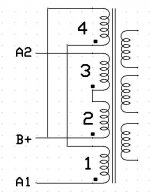
Here is my PP OPT with prim. 4 and sec. 3 sectioning
I measured every winding one by one and also together.
The symmetri is almost 100% in DCR and in Induction. Every winding has almost the same value.
From A1 to Center tap: 1.48H
From A2 to CT: 1.47H and
From A1 to A2 5.9H
With my normal winded OPT the values are:
A1 to CT: 5.74H!
A2 to CT: 5.68H!
Total is over 22H.
Tyimo
Attachments
Hi, Tyimo !
Did you measured output voltage on secondary if transformer (with progressive winding) is connected to sine-wave generator?
I think trafo with progressive winding have incorrect polarity connection between sections 4-1 and 3-2. If you feed 1KHz signal from the generator to A1-A2, and measure voltage on secondary loaded with let's say 100 Ohm resistor, you could calc by output voltage if my version is right - and I'm 99% sure it is (assuming cores and number of turns are the same, and 2nd core is not defect).
Last edited:
- Status
- This old topic is closed. If you want to reopen this topic, contact a moderator using the "Report Post" button.
- Home
- Amplifiers
- Tubes / Valves
- Odd/Crazy output transformer design?