Might be "one core turn" = one layer
Thanks Ilimzn!
I don't understand this.
How can wind the whole primary winding (many hundreds of turns) in only one core turn???
I konw that by toroid wind anyway I have to care about to spread the turns around the whole core.
An ideal toroidal coil has its winding spread over 330 degrees of the core. This leaves ca. 30 degrees gap an the ends of the winding.
I thougt that progressive winding is good for sectioning and for perfect splitting the primary.
Like one half of the core is for the half of the primary windings and the another half of the core is for the rest of the primary. 50%-50%.
Could you show me a picture or a drawing to understand it?
Tyimo

Yes, one core turn = 1 layer, in standard winding terminology.
The schematic for progressive winding posted on the previous page applies usually to high voltage windings, which are split so that no part of the winding near the start overlaps no part of the winding near the end. The voltage differential would be too large for the enamel to withstand.
When this is not the case, a winding can be made by simply putting turns around the core as they come, taking care to spread evenly so that start and end are some degrees apart, this is done to make space for the actual winding leads (especially in the case of thin wire when the enameled wire is extended using standard color coded insulated wire by soldering, and the joint has to remain 'inside' the transformer). This would be done for standard mains transformers.
The other way of progressively winding a toroid was given on the previous pages, where the general schematic posted above is actually 'multiplied' many times over the ring core circumference - basically the wire is put on the core in an 'n turns forward, m turns back' patter, where m<n and usually both n and m are as small as practical for best results. Most modern winding machines can be programmed to do this automatically, on others you have to use manual intervention so winding takes a lot more work. In this way the whole winding is made by starting on one point on the ring circumference, and ending some degrees before the full circle is made. The gap with no turns should be kept as small as possible accounting for voltage differential, because making gaps results in increased leakage inductance. The trick my winder uses is to make the first and last 1-2 turns with the insulated lead wire, or, for larger enameled wire diameters, they use the wire itself as a lead by putting a piece of insulating tubing on it.
Such a winding does not have layers in the traditional sense, it resembles a sort of squashed Pi-would scheme.
In any case, proper preparation is needed for best results, including using the circumference and wire thickness to properly calculate n and m, and set up the machine for that. The winding itself must end up as flat as possible because any iregularity results in increased leakage inductance, and worsening fill factor. Since the transformer is usually going to have more layers of insulation than a comparable mains transformer, being sloppy can result in the central opening becoming too small for the winder head before the transformer is complete.
Optimizing the transformer for more iron, less copper is a good idea, this often tends to become the case because of the central opening needed for all the windings, so the core ends up having a larger than standard radius for a given cross-section (proper calculation is needed of course as the magnetic path length increases).
Thanks Ilimzn!
So, you are suggesting something like on the drawing of post 23.
I just misunderstanded the meaning of LAYER. I thought layer is only one roll of wire around the core.
Do you use any insulation material between the rows in the same layer?
I mean in a non progressive made windings.
Tyimo
Now I understand.The other way of progressively winding a toroid was given on the previous pages, where the general schematic posted above is actually 'multiplied' many times over the ring core circumference - basically the wire is put on the core in an 'n turns forward, m turns back' patter, where m<n and usually both n and m are as small as practical for best results.
So, you are suggesting something like on the drawing of post 23.
I just misunderstanded the meaning of LAYER. I thought layer is only one roll of wire around the core.
Do you use any insulation material between the rows in the same layer?
I mean in a non progressive made windings.
Tyimo
Well, that's how C-cores are made, the only difference compared to toroids, being that when the tape is wound into a core, an adhesive goes in-between, then the core is baked to cure the adhesive, and then it's cut and polished to make the halves. On a toroid, because it's wound, no adhesive is needed in most cases, the core tends to hold iteslf together. However, if it is to be cut, adhesive must be used or the cut ends will simply fly apart. Toroid cores are often used to make clamp-on current transformers, in which case half of the winding is wound on a bit less then half of the core circumference, leaving two gaps, where the core is alter cut once the core and the winding are vacuum molded with epoxy or other similar resins. However, this leaves a stray field inducing gap.
about 25 years ago when toroids were still only becoming popular, there used to be large toroid cores that were actually wound like C-cores, but not cut. This makes for less 'wasted space' for the opening inside the core and smaller total dimensions, and most notably enabled core manufacturers to recycle some of their C-core material with a net saving because of no cutting and polishing. Most winders today make their own core out of tape lamination so this is not so popular any more.
about 25 years ago when toroids were still only becoming popular, there used to be large toroid cores that were actually wound like C-cores, but not cut. This makes for less 'wasted space' for the opening inside the core and smaller total dimensions, and most notably enabled core manufacturers to recycle some of their C-core material with a net saving because of no cutting and polishing. Most winders today make their own core out of tape lamination so this is not so popular any more.
You are funny...., but the question remained the same:Cutting the toroid, bending the legs until it resembles a c-core, winding two straight coils (one per leg), and even as it is for PP, make a very small air gap between core halves....
What is the best way to wind a perfectly split and equal primary windings in a PP toroid?
You are funny...., but the question remained the same:
What is the best way to wind a perfectly split and equal primary windings in a PP toroid?
Again, audio toroids are not done this way. I have audio output toroid, its primary sections are 47 and 55 Ohms respectively, compared to 5K primary impedance this discrepancy is nothing.
If you want fully balanced primary you should take long-bobbin double C core and split it into 2 equal sections.
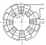
Of course, you can wind segmented toroid (see picture attached), but this construction is not suitable for audio output devices.
Attachments
minimizing leakage inductance/maximizing coupling/symmetry of the pri halves requires them to occupy the same space as much as possible - just like pri-sec
if the capacitive loading effects on bandwidth could be ignored then bifilar or single layer interleaving would be "best" - use the level of interleave and sectioning compromise that meets your requirements - or adjust your requirements to match physically and practically realizable windings
if the capacitive loading effects on bandwidth could be ignored then bifilar or single layer interleaving would be "best" - use the level of interleave and sectioning compromise that meets your requirements - or adjust your requirements to match physically and practically realizable windings
You are funny...., but the question remained the same:
What is the best way to wind a perfectly split and equal primary windings in a PP toroid?
OK I was kidding, but serious at the same time.
Look at the c-core being a stretched toroid; both are strip wound with the best possible orientation of the core, unlike the EI core.
IMHO the c-core has some important advantages over a toroid:
- coils can be wound on straight bobbins; this means full control and precise winding which is not possible on toroids (I speak out of experience as I practice both techniques, that is c-cores for power supply, interstage and output transformers, and special quality small toroids for small signal applications like input transformers, MC step up transformers and my inductive volume control); precise winding on a straight bobbin also means that capacities can at least be controlled;
- it is easy to apply accurate air gaps with c-cores (not only for SE but also important for PP output transformers!).
Great points by pieter...
Making the winding even along the circumference of the toroid core is one of the most important things in quality winding of toroids. Sloppy winding = sloppy results.
If you can balance out currents for a close to zero ner DC flux, then you can use a standard toroid core (gapless).
It is indeed possible to wind for equal resistance on a toroid core, by using techniques mentioned, usually a combination of sectioning and layering/interleaving. In practice, sectioning on a toroid core potentially implies a lot more labor, especially in a PP primary where you need to make uniform windings without unused core length for lowest leakage inductance, and simultaneously insure good insulation and low winding capacitance. The simplest way would be to wind two layers with two semicircular sections each (with some insulation for the ends), sections a and b in one layer, then c and d in the next, section c being wound over section a, section d being wound over section b. Then connect a and d in series to form one half of the primary, b and c in series to form the other half. Sections must be wound progressively.
Another possibility is to split the primary into four equal parts. Wind each 1/4 primary as layers, progressively, one over the other, a, b, c, d. Then connect a and d in series to form one half of the primary, and b,c in series to form the other half.
Needles to say, this is by no means the ideal situation. For one thing, sections/layers are only separated by relatively thin insulation, and because they form one primary winding, interwinding capacitances are no trivial matter. However, even with this technique you get a usable OPT (assuming the core and number of turns is properly calculated and the winding is well done).
Better results are obtainable by using interleaving. It should be noted that properly winding the secondary winding is by no means a trivial affair on a toroid OPT, even less so if it is to have multiple output taps for various output impedances. For this discussion it is important that the secondary has a relatively small number of turns and a far lower voltage differential end to end, unlike the primary. It is also usually connected to ground at some point. This means that the secondary (either as a whole or considered as multiple layers itself) can be used to shield parts of the primary winding from each other, preventing inter-layer capacitances from manifesting as inter-winding capacitances where large AC voltage differentials between multiple layers of the same winding make these capacitances appear much larger. In the above mentioned winding schemes, the sectioned + layered approach would best benefit from having the whole secondary winding placed between the two layers of the primary. Making a tapped secondary for this sort of layout is no simple thing and usually involves multifilar winding. The key, as always, is that if there is a part of the secondary that does not pass current (such as in the case of an unused 8-ohm tap), it should never occupy a discrete section of the core circumference, instead it must be evenly distributed amongst turns that do have current passing through them. Otherwise, parts of windings have different capacitances, and different magnetic coupling to other windings, resulting in all sorts of problems, only one of which is increased leakage inductance.
The 4-layer primary winding scheme is a bit more flexible WRT tapped secondary but still not trivial - the secondary needs to be split into 3 layers. Since secondaries usually have a much lower number of turns, this may lead to imperfect fill factor (seizable gap between adjacent turns) meaning the total secondary occupies more space and can (depending on wire thickness) become a 'bumpy' surface for the next primary layer, making it more difficult to wind the layer evenly. Multifilar winding techniques can help here but increase labor. They do, however, have two extra benefits - it is usually easyer on the winder to wind multiple smaller diameter wire strands, than one large diameter wire, and secondly, this takes care of skin effect. Since the secondary winding resistance is directly in series with the output signal, it is beneficial to keep it as low as feasible, usually meaning thick wire. However, increasing the thickness pushes the ratio of cross-section vs circumference up, which may make skin effect visible at the top end of the audio spectrum. This may not seem significant at first glance, but it should not be dismissed off hand. Toroids have the capacity to be relatively high bandwidth transformers, which may tempt the designer to apply more feedback around the transformer. Ignoring skin effect in such cases may result in nasty surprises - think electrostatic speakers.
Last edited:
Re: ilimzn
Superb exposition, I see why you were emphasizing the interleaving requirement now for a balanced P-P toroid some while back. The complexity of doing it all "correct" though is looking somewhat overboard for an automated toroid winder, without a lot of operator interaction. What bandwidth is achievable on such a toroid versus some of the simpler appoaches like dual bobbins on a C-core or dual bobbins on long E laminations?
Superb exposition, I see why you were emphasizing the interleaving requirement now for a balanced P-P toroid some while back. The complexity of doing it all "correct" though is looking somewhat overboard for an automated toroid winder, without a lot of operator interaction. What bandwidth is achievable on such a toroid versus some of the simpler appoaches like dual bobbins on a C-core or dual bobbins on long E laminations?
Thanks to everybody!
Since long time this is the most useful thread in this Toroid OPT theme.
Accordingly, progressive winding is not so important.
A classical winding (turns by turny ) with a bigger core has more advantages, especially with the 4 part sectioning.
This way I will have simple but effective DCR and inductive ballance.
Tyimo
Since long time this is the most useful thread in this Toroid OPT theme.
The capacitance between two quarters of a PP primary that are wound bifilar, on a 30W OPT (admittedly calculated to go down to 20Hz), is about 65nF. Capacitance between two separately would standrad windings with the same number of turns, separated by the minimum amount of tape insulation is about 2nF. If you want the resosnances of the transformer to be pushed far outside the audio band where you practically do not need to be concerned about them at all, it is obvious what method of winding you have to chose.
Please note that progressive winding to lower layer to layer capacitance only tackles one of the capacitive components in a transformer.
The primary by itself also has a capacitive component, the longer the wire the more capacitance.
Therefore choosing a big core with "little" copper is IMHO always better than a small core with "much" copper (apart from nowadays catastrophic copper prices!).
With the big core / little copper combo the lower capacities and DC resistances (copper losses) make better transformers.
Accordingly, progressive winding is not so important.
A classical winding (turns by turny ) with a bigger core has more advantages, especially with the 4 part sectioning.
If your aim is to balance the DC resistances of the windings, sectioning is better. It will also reduce parasitic capacitances if the sections are interleaved with parts of the secondary winding, although more than acceptable results can be had just by putting a layer of standard insulating tape between the sections. For PP windings, the number of sections must always be even if DCR balance is the aim - the minimum is 4 sections, one half of each half primary per section. Connect the two outer sections in series to get one half of the primary, and two inner sections to get the other half - the mean turn length is the same this way and the total length of wire in each half-primary will be very close, so the DCR will be balanced.
This way I will have simple but effective DCR and inductive ballance.
Tyimo
Last edited:
What bandwidth is achievable on such a toroid versus some of the simpler appoaches like dual bobbins on a C-core or dual bobbins on long E laminations?
Fine up to 100KHz, this is top limit of my sine-wave generator with low output impedance. I don't think it makes any sense to test above 100 KHz.
The data in the Radiotron handbook 4th 1954 ed makes short work. section 5.3 p-211 The ultimate solution to many of the problems is to reduce the primary impedance by using multiple parallel pairs hence less copper for the same quantity iron, also balancing by sectionalising the windings (as you mention) and using kellogs paper for the insulation. Tape is the worst dielectric material. The biggest mistake is to varnish impregate although on transformers with reduced primary impedance the effect gradually diminishes due to lower n.
The effect with push pull o/p transformers which have an inherently high interwinding capacitance is restricted HF response. The squarewave can be upper/lower well formerd but the slew is effected. In general the issue can be forced by higher global feedback which flattens the closed loop response often at the expense of higher frequency thd. This requires a p-p AB output stage to work harder so a higher quiescent current is required to deal with the o/p transformer capacitances.
A dusty file from 50 yrs ago I will try to download pic with text.
richy
Attachments
Fine up to 100KHz, this is top limit of my sine-wave generator with low output impedance. I don't think it makes any sense to test above 100 KHz.
What is the output impedance of your generator, 50 or 600 ohm?
For instance, if you want to measure bandwidth with a 50 ohm generator, you must at least put a resistor in series with the generator output to simulate the tube Rp.
It does make sense to test above 100kHz to see if, and where, and how serious the HF resonance(s) are showing. In my experience measurements up to 200 kHz tell most of what is going on.
This generator have 2 output terminals - 600 Ohm and 5 Ohm. I used 5 Ohm. As for resonance over 100 KHz, I don't care, not audible anyway.
LinuksGuru,
Measuring bandwidth of a tube output transformer with a 5 ohm source does not make sense at all; my two cents that you know this.
Bad, mediocre and top quality transformers differ in HF resonance behavior; optimizing this for a particular application will not give a better measurement but also a better sounding transformer. This has nothing to do with not being able to hear 100 kHz (and another two cents that you know).
The Devil Is In The Details...
The best tube output transformer that I have heard (and it measured out to 50+ kHz) was a custom Sowter exampes(s) that had interleaved multiple parallel primary and multiple parallel secondary windings - the downside is that all windings MUST have exactly the specified number of turns or else a shorted turn is caused.
When done correctly this works.
Eric.
...... that had interleaved multiple parallel primary and multiple parallel secondary windings .....
Eric.
My guess is that the primary sections are series connected, not parallel.
- Status
- This old topic is closed. If you want to reopen this topic, contact a moderator using the "Report Post" button.
- Home
- Amplifiers
- Tubes / Valves
- Odd/Crazy output transformer design?