Hi,
Not so sure we'd all agree on that...
If you'd were to say: a cascode instead of a FET then, yes. Sort of.
While both cascode and penthodes sport very high gain, you're still stuck with the fact that they're not the most linear devices either.
Which is probably where the SLCF comes in, to kill a few birds with one stone. So to speak.
I wouldn't do that. If it's for the sake of showing the frontend of an MC capable phonostage, O.K.
However if you'd want to build it I'd recommend adding the SLCF or another buffer.
Since the RIAA type used is of the split, fully passive type, you just can't leave the last stage open ended; it requires a defined g' to work against.
Cheers,")
A FET is just a pentode without the partition noise.
Not so sure we'd all agree on that...
If you'd were to say: a cascode instead of a FET then, yes. Sort of.
While both cascode and penthodes sport very high gain, you're still stuck with the fact that they're not the most linear devices either.
Which is probably where the SLCF comes in, to kill a few birds with one stone. So to speak.
(just ignore the line stage bit)
I wouldn't do that. If it's for the sake of showing the frontend of an MC capable phonostage, O.K.
However if you'd want to build it I'd recommend adding the SLCF or another buffer.
Since the RIAA type used is of the split, fully passive type, you just can't leave the last stage open ended; it requires a defined g' to work against.
Cheers,
Hi
Here you will find the Conrad Johnson Premier Six head amp and a lot of other things: http://www.pi.infn.it/~federico/further.htm
I have a Music Reference RM4 head amp schematic somewhere. It uses parallelled 6DJ8 halves (one Tube per channel). I can try to find it if anybody is interested.
Torben
Here you will find the Conrad Johnson Premier Six head amp and a lot of other things: http://www.pi.infn.it/~federico/further.htm
I have a Music Reference RM4 head amp schematic somewhere. It uses parallelled 6DJ8 halves (one Tube per channel). I can try to find it if anybody is interested.
Torben
Head amp!
Herrman,
Would you be so kind to post sch. of MR's RM4 head amp?
Regards,
Yugovitz
Herrmann said:Hi
Here you will find the Conrad Johnson Premier Six head amp and a lot of other things: http://www.pi.infn.it/~federico/further.htm
I have a Music Reference RM4 head amp schematic somewhere. It uses parallelled 6DJ8 halves (one Tube per channel). I can try to find it if anybody is interested.
Torben
Herrman,
Would you be so kind to post sch. of MR's RM4 head amp?
Regards,
Yugovitz
Caution on direct coupling grid to MC
I've played with high transconductance tubes at low Vgk for MC use. The grid current becomes a real problem if you direct couple to the MC. If you calculate the tiny signal currents that an MC makes, this grid current is a huge relative DC bias on the MC coils. For example, an MC which makes 0.5mV at 5cm/s (a very high musical level, nevermind at -90dB below this level) will deliver 5 microamps rms into a 100 ohm load. Grid current for a 6C45/6S45 at small negative grid bias can approach this value. Better to run larger negative Vgk which means (for the same Ia) higher Va, and unfortunately higher Pa. But much lower grid current.
If the curves are linear at Vg0 you can ground the cathode and couple the tube straight to the cartridge, one less cap in the signal path.
I've played with high transconductance tubes at low Vgk for MC use. The grid current becomes a real problem if you direct couple to the MC. If you calculate the tiny signal currents that an MC makes, this grid current is a huge relative DC bias on the MC coils. For example, an MC which makes 0.5mV at 5cm/s (a very high musical level, nevermind at -90dB below this level) will deliver 5 microamps rms into a 100 ohm load. Grid current for a 6C45/6S45 at small negative grid bias can approach this value. Better to run larger negative Vgk which means (for the same Ia) higher Va, and unfortunately higher Pa. But much lower grid current.
Hi,
Well if you don't bias the tube it shouldn't be able to generate any significant amount of grid current.
In order for this to work you'd need a tube that's made for this kind of operation.
To the best of my knowledge there's only one that was ever made with this particular purpose in mind, in fact it was even possible to operate it with positive bias but I digress, and that was the original Philips ECC88.
Others that are useable but show other disadvantages such as lessened linearity and higher Req figures are the ECC85/6AQ8 and some nuvistors that are long gone to unobtainium.
But why settle for second best when you can have the best?
Other tubes will either be not linear at Vg = 0 or will leak a tiny amount of current which will indeed prebias the relative cantilever position in the magnetic field a little but for as long as it's not modulated with the signal level and small enough not to fry the coils it's really no big deal.
Better that than sending that tiny signal through the jungle of a coupling cap IMHO.
The major problem with the 6C45-C in that application (Vg = 0) is that I don't really know how it's going to settle down and how stable it's going to be.
Anyone planning on using it that way should burn them in long enough so they're 100% stable. Any tendency to misbehave may cost you a coil.
In short, while the high gm looks tempting, I feel it's better put to service as a driver or amp input tube than for such delicate work in a headamp.
A final word on the ECC88 family of tubes, if you're willing to spend some time digging your heels into the Philips Labs datasheets you'll notice they actually preconditioned tubes for special purposes.
Anyone with a signal generator can "train" a set of ECC88s when they're still unused for a particular service (within reason) after which the best can be selected for MC headamp service.
Whether it's worth it for you ultimately depends only on how good you want your system to be.
Cheers,
Grid current for a 6C45/6S45 at small negative grid bias can approach this value. Better to run larger negative Vgk which means (for the same Ia) higher Va, and unfortunately higher Pa. But much lower grid current.
Well if you don't bias the tube it shouldn't be able to generate any significant amount of grid current.
In order for this to work you'd need a tube that's made for this kind of operation.
To the best of my knowledge there's only one that was ever made with this particular purpose in mind, in fact it was even possible to operate it with positive bias but I digress, and that was the original Philips ECC88.
Others that are useable but show other disadvantages such as lessened linearity and higher Req figures are the ECC85/6AQ8 and some nuvistors that are long gone to unobtainium.
But why settle for second best when you can have the best?
Other tubes will either be not linear at Vg = 0 or will leak a tiny amount of current which will indeed prebias the relative cantilever position in the magnetic field a little but for as long as it's not modulated with the signal level and small enough not to fry the coils it's really no big deal.
Better that than sending that tiny signal through the jungle of a coupling cap IMHO.
The major problem with the 6C45-C in that application (Vg = 0) is that I don't really know how it's going to settle down and how stable it's going to be.
Anyone planning on using it that way should burn them in long enough so they're 100% stable. Any tendency to misbehave may cost you a coil.
In short, while the high gm looks tempting, I feel it's better put to service as a driver or amp input tube than for such delicate work in a headamp.
A final word on the ECC88 family of tubes, if you're willing to spend some time digging your heels into the Philips Labs datasheets you'll notice they actually preconditioned tubes for special purposes.
Anyone with a signal generator can "train" a set of ECC88s when they're still unused for a particular service (within reason) after which the best can be selected for MC headamp service.
Whether it's worth it for you ultimately depends only on how good you want your system to be.
Cheers,
Well if you don't bias the tube it shouldn't be able to generate any significant amount of grid current.
Depends on what you mean by "don't bias". Zero Vgk is indeed a prescription for grid current, since most tubes begin grid current between -1 and 0 volts, especially tubes with geometries like the 6C45. If you have the RDH 4, look at figure 2.9 on page 19.
To the best of my knowledge there's only one that was ever made with this particular purpose in mind, in fact it was even possible to operate it with positive bias but I digress, and that was the original Philips ECC88.
Several tube types were specified for operation at 0 Vgk. Plate current would be specified at zero grid bias, but grid current was still not zero.
...will leak a tiny amount of current which will indeed prebias the relative cantilever position in the magnetic field a little but for as long as it's not modulated with the signal level and small enough not to fry the coils it's really no big deal.
I'm not so worried about pushing the coils out of mechanical position - other forces such at VTF and skating/anti-skating forces will dominate here. I do worry about a DC bias current that is thousands of times larger than the medium- to low-level desired signal currents generated by the MC, since the DC will bias the magnetic circuits: the iron armature and to a lesser degree the outer magnetic circuit. It's a little like keeping the DC currents balanced (cancelled) in a push-pull ouput transformer. A relatively small DC imbalance can increase distortion.
Better that than sending that tiny signal through the jungle of a coupling cap IMHO.
Agreed, perhaps. My point was that it's better still to direct-couple an MC to a grid that is biased negative more than -1.0, so that grid current truly can be ignored.
The major problem with the 6C45-C in that application (Vg = 0) is that I don't really know how it's going to settle down and how stable it's going to be.
Right. Operating point stability in any fixed bias tube circuit is an issue. Those resistors so often used in the cathode circuits (cap bypassed or not) confer bias stability due to negative feedback, which is lacking in these fixed bias scenarios. The 6C45 may be fussy due to grid current, but the ECC88 can be whipped into service here. Just give it enough plate voltage to make Vgk as negative as is practical for a given plate current.
I agree that the ECC88 is probably a more stable choice for direct-coupling and fixed biasing in MC first stage applications.
Hi,
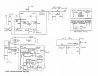
A couple of pages back the circuit diagram is shown for the topology we're discussing.
I probably didn't express myself correctly in the previous post as indeed if you would have Vgk =0 V grid currect would start flowing.
Not much but still....
Yet, as the diagram shows the cathode is held at groundlevel, Vp is constant as is current.
Vg is whatever the MC cartridge requires plus the load and polarizes the grid slightly negative.
If there's still any grid current flowing I sure can't measure it.
The headamp is dead quiet, has a DC coupled input and has been working flawlessly for more than two decades.
Moreover it's dead simple, outperforms any MC xformer I threw at it.
I'm still waiting for the first person claiming they had a better device that would outperfom it after they'd listened to it and I have used the best MC headamps that were available on the high-end market around 1985 prior to refining this circuit.
It has it's origins somewhere midway Eisenson (Tu-be or Not tu-be) and some Skandinavian engineer and was published in a cruder form using 6CW4s in Hi-Fi News around that time.
The Vgk=0 issue has everything to do with how you need to select a proper tube for this application, one that at least looks linear when operated as such.
Unfortunately there aren't many around that qualify and believe me I've looked hard.
Hopefully this settles this issue,
Zero Vgk is indeed a prescription for grid current, since most tubes begin grid current between -1 and 0 volts, especially tubes with geometries like the 6C45. If you have the RDH 4, look at figure 2.9 on page 19.
A couple of pages back the circuit diagram is shown for the topology we're discussing.
I probably didn't express myself correctly in the previous post as indeed if you would have Vgk =0 V grid currect would start flowing.
Not much but still....
Yet, as the diagram shows the cathode is held at groundlevel, Vp is constant as is current.
Vg is whatever the MC cartridge requires plus the load and polarizes the grid slightly negative.
If there's still any grid current flowing I sure can't measure it.
The headamp is dead quiet, has a DC coupled input and has been working flawlessly for more than two decades.
Moreover it's dead simple, outperforms any MC xformer I threw at it.
I'm still waiting for the first person claiming they had a better device that would outperfom it after they'd listened to it and I have used the best MC headamps that were available on the high-end market around 1985 prior to refining this circuit.
It has it's origins somewhere midway Eisenson (Tu-be or Not tu-be) and some Skandinavian engineer and was published in a cruder form using 6CW4s in Hi-Fi News around that time.
The Vgk=0 issue has everything to do with how you need to select a proper tube for this application, one that at least looks linear when operated as such.
Unfortunately there aren't many around that qualify and believe me I've looked hard.
Hopefully this settles this issue,
Frank,
Are you referring to your schematic posted on this thread on 10-03-05?
For that circuit, if it's convenient, would you run a test for me (us)? Unplug your MC so that only the loading resistor (Rx) is in the grid circuit. Measure the voltage across Rx with a DVM capable of measuring low DC voltages accurately, identify the value of Rx, and also measure the plate voltage. I’m curious how much grid current you’re getting with your quartet of 6922s. I’m not trying to make a point with this request I’m just curious what kind of grid currents those four 6922 will have at whatever plate voltage you use. I’ve used several other high-transconductance tubes with very small negative grid bias levels and have experienced pretty high (untenable) grid currents, at least relative to MC signal current levels. But I haven’t tried four 6922s at zero bias yet. If this is too hard, please don’t bother. Thanks in advance.
Are you referring to your schematic posted on this thread on 10-03-05?
For that circuit, if it's convenient, would you run a test for me (us)? Unplug your MC so that only the loading resistor (Rx) is in the grid circuit. Measure the voltage across Rx with a DVM capable of measuring low DC voltages accurately, identify the value of Rx, and also measure the plate voltage. I’m curious how much grid current you’re getting with your quartet of 6922s. I’m not trying to make a point with this request
I’m just curious what kind of grid currents those four 6922 will have at whatever plate voltage you use. I’ve used several other high-transconductance tubes with very small negative grid bias levels and have experienced pretty high (untenable) grid currents, at least relative to MC signal current levels. But I haven’t tried four 6922s at zero bias yet. If this is too hard, please don’t bother. Thanks in advance.Hi,
Brian,
As much as I'd like to help I can't do any meaningful measurements as all the equipment is sitting at a friend's place.
However I can give you the following data from memory, plate voltages may vary a little with tubes and CCDs used but not by more than say half a volt.
B+ post 7824 is +24VDC per rail as is to be expected.
Vp is 22,8VDC each channel (important to select equal IDSS for BF244A or gain will vary between channels)
Rx = Rg = 87R
Note that 2*6922/or equivalent are used in // NOT 4, so two twin triodes in // per channel.
Note sure if that's any help but it's the best I can do for now,
Cheers,
For that circuit, if it's convenient, would you run a test for me (us)? Unplug your MC so that only the loading resistor (Rx) is in the grid circuit.
Brian,
As much as I'd like to help I can't do any meaningful measurements as all the equipment is sitting at a friend's place.
However I can give you the following data from memory, plate voltages may vary a little with tubes and CCDs used but not by more than say half a volt.
B+ post 7824 is +24VDC per rail as is to be expected.
Vp is 22,8VDC each channel (important to select equal IDSS for BF244A or gain will vary between channels)
Rx = Rg = 87R
Note that 2*6922/or equivalent are used in // NOT 4, so two twin triodes in // per channel.
Note sure if that's any help but it's the best I can do for now,
Cheers,
Brian, I wired up a simulation of Frank's circuit with a single 6DJ8 (two sections) and 162 ohms in the grid circuit. 24 volts on the plate. I plugged in several different ECC88 (Siemens date code 887, Amperex Bugle Boy, CCa) and in each case measured -15mV on the grid. Surprisingly consistent.
Eisenson
Hello,
have build the Eisenson on a breadboard, must be in my workshop somewhere.
Have used a russian nuvistor 6S51 or 6S52 (must have a look)and a 2SK170 as current sorce, running from a B+ 40 VDC. From my memory the plate was sitting somewhere at half the B+. Gain was some 30 dB.
As the cathode is grounded I will have a look at the grid current or the voltage across the grid resistor.
Come back to you when i have made this measurings.
Good discussion here, thank you.
Reinhard
Hi
probably will be the best to use battery PS for that purpose...
Considerthe idea to put MC preamp in gramophone chasis to
avoid the long interconnect cables...
If Nuvistors can accept lover Voltages and can opperate vith low gain
6 to 10 that will be the best thing for my oppinion...
*
Tubes with high transconductances does not sound good at all
infact they sound very mediocre...
*
good application of such tubes like ECC88 and so is for the example
to use them like rectifier in tube PS if You go standard PS agains the chemical PS...
*
The most important thing for the low noise and hum PS is to have separate
transformers for the High voltage, heating of gain tube and for the rectifier...
With a minimum 3-4 LC stages in PS line...
In that case probably you can heat the tube with a AC line...
- Status
- This old topic is closed. If you want to reopen this topic, contact a moderator using the "Report Post" button.
- Home
- Amplifiers
- Tubes / Valves
- nuvistor MC step up