Stuart: What are you using for the output transformer primary R?
4k as stated by the OP (I think)
Excellent, thanks! Gotta slog through it. (When I'm more awake)
Stuart
load line distortion cancelling is described in sweet spot article by Nelson Pass
funny that he uses tubes in his describtion
have you thought of looking at a circlotron design ?
Nelson is simply brilliant. If only he could be turned away from the Dark Side. I know there is good in him.

Circlotron is something on my to do list. But the OP is getting a bit overwhelmed at this point, and I think copying and "Pooging" a known excellent design is probably the best path to success. There is certainly LOTS of room for disagreement!
Just downloaded PP Calc. On sale $19. Too sleepy to try it out. Bayme mottorow...
Excellent! Be sure to install it on your work PC. You'll have hours of wasted time; and your creativity will be challenged trying to explain to your boss why your work isn't getting done.
Seriously, I install a lot of TubeCad software on a Windoze notebook because Wine seems to have trouble with it.
No job as of yet...so the boss isn't that much of a problem. I went back to school a couple years ago because we moved to a small town with no local jobs and riding away on the flying bus every Monday was just horrible with a young kid and a hard working wife. I sorely do miss a paycheck and actually look forward to having a job. I actually kinda like programming and having a job will mean I actually have a justification for doing it. I am actually working on something really cool right now for my "capstone" project for my degree but still somehow seem be spending so much more time fiddling with tubes. Last semester I wrote an app that will do mesh current analysis in hopes that it would help me learn more about tube circuits. It didn't help very much...just kicked my ***.
I'd love to have the Morgan Jones books but they're expensive. I'm going to give it a go with stuff off tubebooks.org, starting with Inside the Vacuum Tube by Rider.
Progressive Optimization of Generic Equipment. Took me a moment to find that one. Good description of how I go about many things (and how software is developed).
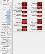
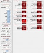
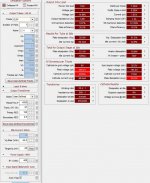
Stuart: Thanks for the screen shots, the first thing that I notice is that your PP calculator GUI is totally different than mine! A few screen shots:
My PP calc GUI has a box for transformer primary DCR....that impacts power out.....
So the first two screen shots are with 31.9ma, 400V, 4K OT with 300R and 100R primary, and the third is with 400V, 60ma, 4K and 100R.
Also, for reference, here is the link for Duncan Amps TDSL for EL34. Notice last entry in the table is AB1 PP triode, 400V, 65-71ma, 16.5W, 3% THD.
TDSL Tube data [EL34]
Attachments
Last edited:
Why carbon resistors in certain positions? Is this purely a tone issue or is there a technical reason?
A technical reason......since they are powdered carbon squished together instead of metal film wrapped around a core, they are non-inductive. They are there to prevent oscillations. That's also why you need to clip the lead short before soldering, so the lead doesn't act like an antenna and so they do not resonate.
Metal film grid stoppers can work also, depends on the application. Try both once you get a scope and can see what's going on. Some folks leave them out entirely (look at Poinz' designs).
Rev 3 looks sweet, could also use carbon comps for the triode connecton on the output tubes, may wish to measure the voltage drop across the output tube cathode resisters for bias check, looks like tied to ground..... I'm wierd, and like option of cap input coupling, always include it in PCB design and if I wish it can be bypassed or not installed....
I use a nixie tube and a 6 position dual switch, one bank switches the amp meter to the individual tube resistors or nothing and the other bank powers the different segments on the nixie tube. It displays what tube is being monitored....
I use a nixie tube and a 6 position dual switch, one bank switches the amp meter to the individual tube resistors or nothing and the other bank powers the different segments on the nixie tube. It displays what tube is being monitored....
Rev 3 looks sweet,
Wow, I'm actually getting there!?!?! Cool. Time to play with PSUD and the PP Calculator a bit.
I'm trying to get my hands on a scope and signal generator somehow.
I use a nixie tube and a 6 position dual switch, one bank switches the amp meter to the individual tube resistors or nothing and the other bank powers the different segments on the nixie tube. It displays what tube is being monitored....
That sounds cool but I think I'll leave that for next year.
Actually, I was just thinking that it would be super cool to somehow rig up a line of magic eye tubes with each acting as a level meter for a certain frequency -- kinda like the silly digital things that car stereos have these days...except I think tubes would be a whole lot more fun to watch.
CC resistors....some swear by them, others swear at them
Futher clarifying my post #68 above........that's for grid stoppers (and the CCS gate stopper)
Other folks use CC resistors in other places especially in guitar amps for tone. Poinz' is calling out a 10R CC for the cathode R in the MM. They can also act as a pseudo-fuse in that position if something fails causing the tube to conduct fully. When acting as a fuse in a failure condition, they been known to occasionally catch fire.
Revision 3 looks good. Let's see your bias pot design. If you can, try and rig up a meter so you can balance the bias pots for zero offset bias current in the transformer. Citation II has this meter setup. Actual, exact bias current isn't that critical. But balance between the two is. No imbalance current in the OPT is any good.
Ditto on stopper installation, body as close to pin/device body as possible.
A friend was using metal films for his stoppers and getting a local AM radio station in his rig. Switched to carbon comps and the problem was gone. No other changes. Carbon comps are fine as long as no appreciable current is flowing through them (grids and gates of Class A or AB1). When current is flowing, avoid carbons for tonal reasons.
Are you soldering yet? LOL!
Thanks all. Not soldering this yet. I still have a PS to do!! I also want to plan the physical layout carefully, draw up plans for a cabinet, and mill the top plate before soldering. I want to take my time a bit, actually enjoy the process, and do things right. I am working on a guitar amp mod, converting a Maggie 196 to RH84, and recapping the occasional console pull so the iron gets some exercise.
Stuart: Thanks for the screen shots, the first thing that I notice is that your PP calculator GUI is totally different than mine! A few screen shots:
My PP calc GUI has a box for transformer primary DCR....that impacts power out.....
So the first two screen shots are with 31.9ma, 400V, 4K OT with 300R and 100R primary, and the third is with 400V, 60ma, 4K and 100R.
Also, for reference, here is the link for Duncan Amps TDSL for EL34. Notice last entry in the table is AB1 PP triode, 400V, 65-71ma, 16.5W, 3% THD.
TDSL Tube data [EL34]
Thanks BW.
Looks like it's time for me to pony up and send JB another $19. I wish he'd email out to his customers each time he updates his software. He'd make more money with that sort of advertising.
Hope this runs better under Wine.
Stuart
Thanks all. Not soldering this yet. I still have a PS to do!! I also want to plan the physical layout carefully, draw up plans for a cabinet, and mill the top plate before soldering. I want to take my time a bit, actually enjoy the process, and do things right. I am working on a guitar amp mod, converting a Maggie 196 to RH84, and recapping the occasional console pull so the iron gets some exercise.
Yeah, that stuff is important.
I remember my first big project. Dad took a picture of me.
Attachments

OK, I'm starting to play with PSUDii a bit. So I now know that there is essentially no documentation. Fair enough, I'll get there. I worked up a CRCLCRC that gives me ~400V with a 60ma constant current. It only has a current tap for the power tubes now. Still working and also need to work with the PP calc to figure out exactly what I want. I have many questions about PSUD and PS design. Of the top of my head...
And beyond that...
I'm considering going with monoblocks. If I do that I still need the same HV capability but with less current for each PT, right? You guys pointed me at PTs with about 700V. I'd need to stick with that but only need to handle the current from 2xEL34 and one each 6SN7 and EF86 (assuming SS rectification).
On that note: Why 700V when I'm only looking for 400V on the power tubes?
The suggested Antek has no center tap so would be bridge rectified while the Edcors with center taps would be full wave, correct?
I don't know what I'm doing with the different diode parts. I just stuck with the standard 1N4007 and it said the rectifier PIV was exceeded. I changed it to 1N4007x2 and it stopped complaining. Is there a "best" diode choice?
I think I am going to model and put the sockets in for tube rectification so I can try that out later on.
- What am I learning/doing by choosing either a current tap vs load for my terminal component?
- What does having a step in the current after a time delay model (i.e. what should I do with it)?
- How much ripple is acceptable in terms of amplitude/frequency?
- How do I know what to enter for the transformer parameters when I haven't got them yet? Just put in the voltage and current capacity? I found a post that said regulation should be b/w 10-12%. Would it be different than this? Different depending on an EI or toroid transformer?
And beyond that...
I'm considering going with monoblocks. If I do that I still need the same HV capability but with less current for each PT, right? You guys pointed me at PTs with about 700V. I'd need to stick with that but only need to handle the current from 2xEL34 and one each 6SN7 and EF86 (assuming SS rectification).
On that note: Why 700V when I'm only looking for 400V on the power tubes?
The suggested Antek has no center tap so would be bridge rectified while the Edcors with center taps would be full wave, correct?
I don't know what I'm doing with the different diode parts. I just stuck with the standard 1N4007 and it said the rectifier PIV was exceeded. I changed it to 1N4007x2 and it stopped complaining. Is there a "best" diode choice?
I think I am going to model and put the sockets in for tube rectification so I can try that out later on.
OK, I'm starting to play with PSUDii a bit. So I now know that there is essentially no documentation. Fair enough, I'll get there. I worked up a CRCLCRC that gives me ~400V with a 60ma constant current. It only has a current tap for the power tubes now. Still working and also need to work with the PP calc to figure out exactly what I want. I have many questions about PSUD and PS design. Of the top of my head...
- What am I learning/doing by choosing either a current tap vs load for my terminal component? Choose by type of load. If you have a stage with a CCS load, either in the plate or cathode, choose current tap; if you have a varying load, such as a resistive loaded stage, choose the resistive value/setting. Class AB output stages will have an idle current and a maximum current. I've been doing simulations with both as extremes and looking for the voltage sag.
- What does having a step in the current after a time delay model (i.e. what should I do with it)? If you are using a relay to soft start your amp, it's helpful. I'm sure there are other purposes.
- How much ripple is acceptable in terms of amplitude/frequency? Depends on the input signal level. In first stage phono applications less than 1mV probably. In push pull output stages, probably several volts are okay.
- How do I know what to enter for the transformer parameters when I haven't got them yet? Just put in the voltage and current capacity? I found a post that said regulation should be b/w 10-12%. Would it be different than this? Different depending on an EI or toroid transformer? You need actual parameters or it's a guess.
And beyond that...
I'm considering going with monoblocks. YEAH! The way to go. If I do that I still need the same HV capability but with less current for each PT, right? True. You guys pointed me at PTs with about 700V. I'd need to stick with that but only need to handle the current from 2xEL34 and one each 6SN7 and EF86 (assuming SS rectification). Correct whether SS or VT rectifiers.
On that note: Why 700V when I'm only looking for 400V on the power tubes?
Not 700V, but 700VCT. PSUDII uses half the transformer value if you are using full wave, not bridge rectification. In other words, if you have a 700VCT transformer and you are choosing either SS or VT full wave rectifiers, set transformer voltage as 350. Raw DC B+ would then be around 430V. The Antek has TWO 350V windings. Connect them in series to create a 700VCT transformer.
The suggested Antek has no center tap so would be bridge rectified while the Edcors with center taps would be full wave, correct? See above.
I don't know what I'm doing with the different diode parts. I just stuck with the standard 1N4007 and it said the rectifier PIV was exceeded. I changed it to 1N4007x2 and it stopped complaining. Is there a "best" diode choice? Yes, but you already know that answer. LOL.
I think I am going to model and put the sockets in for tube rectification so I can try that out later on. Two octal per channel gets it done, about $6.
I worked up a CRCLCRC that gives me ~400V with a 60ma constant current. It only has a current tap for the power tubes now. Still working and also need to work with the PP calc to figure out exactly what I want. I have many questions about PSUD and PS design. Of the top of my head...
Well, after reading this I'd say you are way along the PSUDII learning curve. I would start with a CLCRCRC. That way the output tubes get the benefit of the choke.
I'm too much of a newbie/knucklehead to be able to use resistive loads, although I suppose if you know the B+ voltage and current draw, Ohm's law will get the answer. I just use current taps for each stage.
- What am I learning/doing by choosing either a current tap vs load for my terminal component?
What does having a step in the current after a time delay model (i.e. what should I do with it)?
It allows you to check if your supply design is sufficiently damped. Put a 20-30ma step after about 5 seconds or so, and see if the step causes the voltage to ring (a bad thing). You don't want an under damped supply.
Since it's PP you can live with a little. I usually shoot for 10's of ma. You can zoom way in on the waveform (zoom in about 4 times) and read it off of the Y axis. You can also read it out of the data fields if you set a starting delay long enough to allow the B+ waveform to be steady-state, ie flat.
- How much ripple is acceptable in terms of amplitude/frequency?
If you click on the three dots in the drop down window for transformer voltage and resistance, you can enter various parameters and PSUD will calculate/estimate resistance, etc.
- How do I know what to enter for the transformer parameters when I haven't got them yet? Just put in the voltage and current capacity? I found a post that said regulation should be b/w 10-12%. Would it be different than this? Different depending on an EI or toroid transformer?
Also see the first post here:
diytube.com :: View topic - The Dumpster Transformer Topic
You can back-calculate the transformer impedance from the chart in the article, it'll be close. Keep in mind that higher current rated transformers will have lower resistance than lower current rated transformers, and this resistance impacts the output impedance of the supply. Using a tube rectifier usually also requires significant transformer resistance, and can usually results in a higher output impedance supply than SS rectification.
And beyond that...
I'm considering going with monoblocks. If I do that I still need the same HV capability but with less current for each PT, right? You guys pointed me at PTs with about 700V. I'd need to stick with that but only need to handle the current from 2xEL34 and one each 6SN7 and EF86 (assuming SS rectification).
Yes, same voltage, half the current compared to a stereo design. Applies to tube or SS rectification.
On that note: Why 700V when I'm only looking for 400V on the power tubes?
As already mentioned, it's because it's FWCT.
The suggested Antek has no center tap so would be bridge rectified while the Edcors with center taps would be full wave, correct?
Correct.
I don't know what I'm doing with the different diode parts. I just stuck with the standard 1N4007 and it said the rectifier PIV was exceeded. I changed it to 1N4007x2 and it stopped complaining. Is there a "best" diode choice?
That's fine, or just use one 1N4007 and live with the messages. I use Fairchild stealth 8A 1200V FREDs bypassed with 10nf 2kv caps in most of the supplies I've built (all three..). If you want to go upscale you can use 1200V Schottky's, but they are expensive.
I think I am going to model and put the sockets in for tube rectification so I can try that out later on.
If you go SS rectification, you can always use the extra socket for an amperite time delay relay; allows filament warm-up before applying B+ and looks cool.
One more thing, if you do a CLC supply, you can vary the B+ voltage by using a small (usually less than 10uf down to less than 1uf) first cap. The B+ can be varied between 90% of the transformer voltage (mimicking a choke input design) and 141% of the transformer voltage (a cap input design).
Alright, lets see if I figured anything more out...
Antek 360V secondaries: wire in series (with same colored wires tied together?) and get a 720VCT device which you could use full-wave rectification on OR get the pretty much the same B+ from one of the secondaries with a bridge? Would the available current be the same in each case?
(If the above is not totally bassackwards...) Could you also create a bridge across one side of a center tapped 720VCT device (e.g. like the Edcors) to again get pretty much the same B+ as above?
And in case I'm still not totally wrong...Couldn't one essentially run two separate power supplies off of either of the aforementioned transformers using bridges and if so would there be any benefit to this over using full wave for a single PS and running two channels off of it?
It seems there there aren't a lot of "same voltage but half the current, size, and price" transformers out there (at least Antek's shielded flavor and Edcor -- Antek does have the 2t350 I think). Kinda looks like building monoblocks is likely to practically mean getting two of whatever PT you would use in a stereo amp.
Playing with PP calc...seems a target around 60ma and 400V on the plate is good. Appears that the datasheets are suggesting ~70ma but this is pushing it, no?
Can anyone point to a schematic that demonstrates a good bias pot scheme for individually biasing each tube?
Thanks again y'all.
- Status
- This old topic is closed. If you want to reopen this topic, contact a moderator using the "Report Post" button.
- Home
- Amplifiers
- Tubes / Valves
- Noob. Help PP EL34 / EF86 both as triode schem.