Also, you will need more than -30V to bias the EL34's. Shoot for a range of -30 to -40V or so. Separate bias pots for each tube are handy, and consider designing the bias supply to fail safe if the pot wiper lifts.
.
Why then does the EL-34 Music Machine use -30V?
The schemo you posted is fixed bias..........cathode bias will have much larger cathode R's and no negative rail.
Yep, I had been reading and didn't read enough. My rev1 was fixed bias but with no adjustment (though it could've been shown in the PS)...so I need to to make it adjustable. Looking at the EL34 MM schemo I might have also answered my previous question...is 30V there some midpoint in the range offered by the pot or something?
mfaughn,
2) DC coupling as many places as possible (1st stage-phase inverter) is a goal to shoot for. Don't add signal circuit caps where not needed.
Which is what I think I have in what I've drawn so far, right?
The .1uf coupling PI to EL34 is kinda low based on what I see in other schematics but I own some nice caps in that value so was hoping to use them -- at least try them.
3) IF you do add a CCS in the tail of the phase inverter (6SN7), THEN the plate loads can and should be equal, as stated by roline. The numbers you have worked for Eico. ;^)
Which makes me wonder why the plate loads are different in the first place. Why does one do that in a PI?
7) Do you need the input pot? If you are using a line stage of any sort, best not to add another pot. If you are building an integrated amp, that is, including a volume control and selector switch, I'd use a smaller value pot, especially if you use the EF86 in triode mode. In pentode, Miller capacitance is not an issue, in triode, you have to watch out or your volume pot becomes a tone control.
8) Why not use the EF86 in pentode? It has none of the pentode edge and eliminates the Miller problem. The amp has lots of gain as designed by Eico. Probably it will still be enough with the EF86 in pentode, but you may need an active line stage depending on your source output.
Until I build a buffer then this amp will likely be fed directly from a DAC which only has a software volume knob. The DAC does 2V at max output. I like having a real knob somewhere. I might put a bypass switch on the input pot.
10) If you are considering compatibility with KT88/6550 types, you'll need a -75V bias supply, reduce those output grid leaks to 100k and increase the coupling caps to 0.47uF.
11) That's all the easy stuff, wait until you ask about caps, resistors, wire, chassis materials, etc. LOL!
Stuart
It should be easy enough to change the bias supply later, right? just a few resistors?
I'm gonna keep it simple on caps, resistors, wire, etc. Nothing fancy unless I already have it. Chassis will be wooden. Wood on advice from a friend that I completely trust on the matter (he's a very well respected amp designer).
Oh, one more thing. If you can, build a completely separate power supply for the input stages. No need for any fancy regulation, just simple and straightforward, but:
Tube rectify
Good electrolytics (Nichicon PW series are cheap and excellent) or good film caps like the Mundorf M-Tube Caps
Choke filtering
EI core transformers
For the output (PP) section, a toroid is probably okay, but in general, the low pass filtering given by an EI core transformer is to your benefit.
If you must use a toroid, be sure it has an electrostatic shield and ground it. Antek has those in the product line up.
Damper diodes are best, after that other people can tell you which VT rectifier they like best.
Stuart
The power tranny I have to work with does have a 48V tap. I *think* I can use that for a CCS so I may go ahead and do that. It don't think it has a 5V tap but I do want tube rectification so I may need to figure that out. For now I'm trying to mostly minimize expenditure and complexity so I may wait until later for a separate input PS.
I do think I need an (inexpensive) scope.
Note: Just because I'm not asking about something now, doesn't mean I'm not considering everything that is being suggested to me. I'm implementing suggestions that I *think* I understand.
Which is what I think I have in what I've drawn so far, right? Correct
The .1uf coupling PI to EL34 is kinda low based on what I see in other schematics but I own some nice caps in that value so was hoping to use them -- at least try them. Yeah, they're a little small, but try out your HQ caps; if bass response is lacking, you can increase cap size later. Smallest cap sounds best (within the same product line) except for bass extension.
Which makes me wonder why the plate loads are different in the first place. Why does one do that in a PI? The LTP phase inverter isn't balanced. An imbalance is created by the loss of cathode follower (the first half) gain due to the cathode resistor being less than infinite resistance. It's partially made up for by the 2nd tube having a gain of mu+1, but not enough. Using the CCS gets the gain close enough that the plate resistors can be equal.
Until I build a buffer then this amp will likely be fed directly from a DAC which only has a software volume knob. The DAC does 2V at max output. I like having a real knob somewhere. I might put a bypass switch on the input pot. Okay, consider an LDR attenuator. Look up the Lightspeed thread. They are affordable and sound fantastic. The downside is the low value of about 7k. It will put demands on your CD player, so it should have an output Z of <100R and a large coupling cap or DC coupling. Well worth every moment of effort, however.
It should be easy enough to change the bias supply later, right? just a few resistors? Sure, as long as your raw B- is great enough. If your 48V "tap" is a separate winding, a doubler will get you plenty of B-.
I'm gonna keep it simple on caps, resistors, wire, etc. Nothing fancy unless I already have it. Chassis will be wooden. Wood on advice from a friend that I completely trust on the matter (he's a very well respected amp designer).
Excellent advice from your amp designer friend!
For resistors, use IRC RN60D and GS-3 as needed, they fit the definition of cheap and they sound great, no thinness or HF brightness. Lots of affordable cap choices. Avoid the Solen metalized. Wima film and foil FKP are nice as are lots of others in the affordable ranges. Look up some cap reviews, lots of useful information. For chassis wire, a very affordable choice is Belden 1701LC. For $1.35/foot, you get 8 feet of 24 gauge solid copper Teflon insulated wire (it's a multi-conductor cable). Don't pay extra money for silver plated copper in Teflon. It sounds tizzy. Solid silver is nice sounding, though. For larger gauge needs, I like the Cardas wire, but it's a little pricey. 23.5 ga @ $1.15/foot; 17.5 ga @ 1.45/foot, PITA to terminate, but wonderful sound. Good source is Handmade Electronics, fast delivery and nice prices.
The power tranny I have to work with does have a 48V tap. I *think* I can use that for a CCS so I may go ahead and do that. The CCS doesn't need another tap. It simply hooks to the cathodes and ground. A 10M45S will work just fine. All you need is a 1k carbon comp or carbon film stopper and a "set" resistor. Look up the data sheet, it's really simple. It don't think it has a 5V tap but I do want tube rectification so I may need to figure that out. Easy! Damper diodes are affordable, look up 6DN3, for instance, (check out ESRC or vacuumtubes.net) and they have 6.3V filaments, indirectly heated with huge cathode-heater differential allowed. So you can use your standard filament winding. Just watch the current, they do draw quite a bit. For now I'm trying to mostly minimize expenditure and complexity so I may wait until later for a separate input PS. Sounds like a good plan, just arrange your layout to provide for the future addition of a separate supply and you'll be golden!
I do think I need an (inexpensive) scope. Yup! And a signal generator.
Best of luck to you. Keep us posted!
Note: Just because I'm not asking about something now, doesn't mean I'm not considering everything that is being suggested to me. I'm implementing suggestions that I *think* I understand.
Last edited:
Why then does the EL-34 Music Machine use -30V?
Well, it uses around -30v to -40v depending on what brand of EL34's you pop in there.
Yep, I had been reading and didn't read enough. My rev1 was fixed bias but with no adjustment (though it could've been shown in the PS)...so I need to to make it adjustable. Looking at the EL34 MM schemo I might have also answered my previous question...is 30V there some midpoint in the range offered by the pot or something?
Yes, ohms law is your friend. Do the calcs for -66V to ground to get the current, then calculate the voltage at the various R's with the pot tuned fully in each direction. The suggestion of using a higher negative bias voltage is a good idea if you want to try kT88's or 6550's later. Keep in mind that the EL34 needs about 30V of swing at the grid for full output and the KT88 needs about 50V (both for AB1 conditions, ie no positive grid current).
So the KT88's would require -50 to -60V or so bias.
A few other points on the bias circuit: Poinz' schemo is not fail safe if the pot wiper lifts. That would allow the output tube to be full on, resulting in bad things happening. I actually had a bias pot puke in my music machine when I took it to the last burning amp festival, but the failure was open to ground so the tube ended up in cut-off, ie not conducting, got lucky. I think this failure is pretty rare, although the consequences are bad.
Once you calc out the values of the pots and R's for the bias circuit, it's pretty straightforward to do separate pots for each tube if you want, just keep the current to ground a couple of ma or less.
Which is what I think I have in what I've drawn so far, right?
Yes, the posted design is fixed bias...
The .1uf coupling PI to EL34 is kinda low based on what I see in other schematics but I own some nice caps in that value so was hoping to use them -- at least try them.
That small cap may limit your low freq cutoff. Easy enough to change to .22 or .33u.
Which makes me wonder why the plate loads are different in the first place. Why does one do that in a PI?
To get symmetrical voltage swings, since with a R in the tail you need a little imbalance to get sym voltages. Use a 10M45S in the tail and equal value R's in the anode loads to maximize performance. There are several recent threads here on the subject. I think one recent discussion started in TubeMack's 5-20 KT88 thread and then SY started a new thread by experimentally proving the theory.
You don't need a negative voltage for the CCS if you direct couple the EF86 to the LTP as you have in the schematic, since the LTP input is at an elevated voltage. In Poinz's MM, the input to the LTP is not elevated, so you need some negative voltage, ie -66V to make the 10M45S happy.
Until I build a buffer then this amp will likely be fed directly from a DAC which only has a software volume knob. The DAC does 2V at max output. I like having a real knob somewhere. I might put a bypass switch on the input pot.
Or two inputs, one with a fixed 100K R and another with a 100K pot.......
Before you break out the soldering iron, I would recommend checking how much input sensitivity you'll end up with using a triode and pentode wired EF86 with and without feedback.
It should be easy enough to change the bias supply later, right? just a few resistors?
Yes, and a larger value pot will give more adjustment. It's a good idea to have enough negative voltage to put the tubes into cutoff when bringing the amp up the first time and for troubleshooting.
I'm gonna keep it simple on caps, resistors, wire, etc. Nothing fancy unless I already have it. Chassis will be wooden. Wood on advice from a friend that I completely trust on the matter (he's a very well respected amp designer).
The power tranny I have to work with does have a 48V tap. I *think* I can use that for a CCS so I may go ahead and do that. It don't think it has a 5V tap but I do want tube rectification so I may need to figure that out. For now I'm trying to mostly minimize expenditure and complexity so I may wait until later for a separate input PS.
The 48V tap should be plenty for EL34 bias, but as already mentioned, will probably need to be voltage doubled for KT88 duty.
I would use SS rectification but that's just me..pulling 200-250ma and 400v with a typical tube rectifier will require a fair bit of PS impedance to keep the rectifier happy, which may not be a good thing.
Do the PS design in PSUDII. Panasonic TS-HA (400V), TS-HB (450V) and TS-UP (500V) caps are a good choice for the PS and very affordable.
I do think I need an (inexpensive) scope.
......and signal generator, and a couple of voltmeters. Check out your local Craigslist.
Note: Just because I'm not asking about something now, doesn't mean I'm not considering everything that is being suggested to me. I'm implementing suggestions that I *think* I understand.
Here's where I am now. Still working at it but I thought I'd put it up anyway. A couple components didn't quite get printed to pdf correctly but its still clear what is going on. I am pretty sleepy during some of the fiddling I'm doing. Working on this is more fun that schoolwork...its becoming a problem.
What is the purpose of the network in the supply to the EF86 (I just copied it from the HF60)?
What is the purpose of the network in the supply to the EF86 (I just copied it from the HF60)?
Attachments
Here's where I am now. Still working at it but I thought I'd put it up anyway. A couple components didn't quite get printed to pdf correctly but its still clear what is going on. I am pretty sleepy during some of the fiddling I'm doing. Working on this is more fun that schoolwork...its becoming a problem.
What is the purpose of the network in the supply to the EF86 (I just copied it from the HF60)?
Looking good. A few notes:
R1 is a grid stopper, it should be at least 300R and up to the factory 4.7k. Probably not critical in pentode, but a big value in triode will give you a HF rolloff. 4.7R will do nothing. Remember, stopper resistors need to be carbon, preferably carbon comp.
You still need the cap from the second 6SN7 grid to ground.
I can tell you drew this using the ubuntu OS. LT Spice screws up and forgets the occasional circle around a tube.
The network in the plate circuit of the EF86 is a HF rolloff to limit bandwidth. If you use the EF86 in triode, I don't know if the network is needed at all, or if it needs to be adjusted. Your scope will be your pal here.
R2 is correct at 1k, carbon.
P3 should be a 10+ turn pot for reliability and smooth adjustment. It could probably be 100R if R7 were 150R or so. Try to set the 10M45S (which is actually an IC) to 10mA or so. Check to see that you have around 120V-150V across the 6SN7 (5mA per side).
Add a 1k resistor in the tail of the 6SN7 cathodes, above the 10M45S. According to Stuart Yaniger, this adds a bit of isolation of the CCS to the audio circuit, if I remember correctly; ditto for SS CCS plate loads.
6SN7 plate loads will dissipate about 3/4 watt. Use GS-3 IRCs for stability (Mills are even better, but cost 10x+).
C1 & C2 must be 0.47uF-1uF for full bass performance with 100k grid leaks.
Probably a good idea to install grid stoppers on the EL34s. Maybe 1k-4.7k.
Suggestion:
Buy a copy of John Broskie's (Tube Cad) Push Pull Calculator. It will allow you to experiment (simulate) with various B+ voltages, transformer loading, bias points, etc. to fine tune power & distortion. It's cheap ($29!) and insightful.
I did a quick simulation using your 400V, 4k load and other standard assumptions. Power out is 25 watts at the onset of grid current when bias is 60mA per tube. To get that 60mA requires a negative bias of 40 volts. so, in light of that, I may suggest a -50v bias supply rather than my earlier suggestion. Distortion is predicted to be 4.27% 3rd and 0.09% 5th. Of course, that's without NFB. That is also idling the tube at 86% of plate rating and at full power, the tube is slightly over maximum plate rating.
Stuart
FWIW, here are the specs on the PT I have.
P: 117V@ 1.8A
S: 140V@ 0.85A AC
S: 6.3V@ 4.4A
S: 6.3V@ 3.8A
S: 48V@ 0.13A DC
Also re-mulling over the sand rectification option.
I started looking at damper diode info. I really need to play with PSUD before making any PS decisions I think.
P: 117V@ 1.8A
S: 140V@ 0.85A AC
S: 6.3V@ 4.4A
S: 6.3V@ 3.8A
S: 48V@ 0.13A DC
Also re-mulling over the sand rectification option.
I started looking at damper diode info. I really need to play with PSUD before making any PS decisions I think.
FWIW, here are the specs on the PT I have.
P: 117V@ 1.8A
S: 140V@ 0.85A AC
S: 6.3V@ 4.4A
S: 6.3V@ 3.8A
S: 48V@ 0.13A DC
Also re-mulling over the sand rectification option.
I started looking at damper diode info. I really need to play with PSUD before making any PS decisions I think.
Okay, with 140VAC secondary, a doubler is needed. with 140VAC, 1N4007 as rectifiers and an assumed load of 240mA (output tubes idling only, or in Class A portion of operating), the B+ is 315V. At full power, we should be looking at 300mA load. At that current, B+ droops to 301V assuming the transformer has a secondary resistance of 20R.
You don't have 400V to work with.
May I suggest an inexpensive toroid from Antek? AS-4T360
This includes the electrostatic shield. At 550mA, voltage sag won't be a problem. Two 4A 6.3V windings and you can run the 6A outputs, 0.4A EF86s and 1.2A 6SN7s and have a little cushion. you'll still need another filament transformer for the rectifiers. The damper diodes can handle as much as 400mA sustained, so that's not a problem. This Antek costs $54.
Stuart
A few more things.......
As mentioned, your power transformer probably won't cut it. Also check out Edcor's power transformer offerings, lots of choices and affordable, but typically a 4-6 week lead time. Check out something like the XPWR129-120 or XPWR127-120. There are lots of other choices there, the above was from a quick look.
http://www.edcorusa.com/category/37-xpwrseries.aspx?pageindex=1
Solder the grid stopper R's as close to the tube socket as possible, ie cut the lead close to the body before soldering. Carbon Comp is a good idea.
A 1K gate stopper on the 10M45S should be fine.
For 2W or 3W anode resistors, I've been using Vishay PR03/PPC series parts at about 40 cents each from Digikey. They are rated for 750V.
I'm definitely learning more through this process than I would by collecting the parts for the Music Machine and going at it with a soldering iron.
I'm gonna have to tear myself away and get some other stuff done...later.
So if I go with SS rectification the Antek AS-4T360 will cover all my PS taps, right?
I will try and get the PP Calculator. Was that 25W/channel? I don't really need that much. Would lowering the EL34 supply translate to lower output and lower distortion (wild guessing here)?
Is there a big SQ advantage with the Edcor power tranformers? If so why? I see that the two suggested have bias voltage taps. They also have 12V or 18V taps. Would I have a use for those in this project?
I will be at my in-laws for the entire month of June so realistically won't get very far into the soldering stage until mid July at the earliest. That leaves me quite a bit of time for learning / planning / collecting parts. I might start on a bit of woodwork for it in May though.
I'm definitely learning more through this process than I would by collecting the parts for the Music Machine and going at it with a soldering iron.
I learned loads by building the MM.......it's the difference between reading about how to ride a bike and riding a bike...
I will try and get the PP Calculator. Was that 25W/channel? I don't really need that much. Would lowering the EL34 supply translate to lower output and lower distortion (wild guessing here)?
25WPC for a pair of triode EL34's seems high (assuming AB1 operation), although KT88's in triode should do 25W no problem. Poinz' EL34 MM does about 14W or so.
Lower B+ = lower output power for sure, distortion depends on the load line.
Is there a big SQ advantage with the Edcor power tranformers? If so why? I see that the two suggested have bias voltage taps. They also have 12V or 18V taps. Would I have a use for those in this project?
I suppose the SQ of power transformers is very debatable....Yes the two selected have bias taps, and I wouldn't think you'd need the other taps but you never know. There are a few other good choices as well I'm sure. If you want to do tube rectification then you'll need about 40V or so more transformer secondary voltage than for SS rect.
You want a PS with low output impedance to provide the current when needed....PSUDII is your friend here.
I'm definitely learning more through this process than I would by collecting the parts for the Music Machine and going at it with a soldering iron.
I'm gonna have to tear myself away and get some other stuff done...later.
So if I go with SS rectification the Antek AS-4T360 will cover all my PS taps, right?
I will try and get the PP Calculator. Was that 25W/channel? I don't really need that much. Would lowering the EL34 supply translate to lower output and lower distortion (wild guessing here)?
Is there a big SQ advantage with the Edcor power tranformers? If so why? I see that the two suggested have bias voltage taps. They also have 12V or 18V taps. Would I have a use for those in this project?
I will be at my in-laws for the entire month of June so realistically won't get very far into the soldering stage until mid July at the earliest. That leaves me quite a bit of time for learning / planning / collecting parts. I might start on a bit of woodwork for it in May though.
Listen to boywonder, he has good advice.
The Edcor is probably better than an Antek toroid, sonically. And they are pretty. The PT is a power line noise filter, sort of. Toroids are wide band, EI, not so much. Keep power line noise out of your amp. I mentioned Antek because they are affordable, quick to deliver and seem pretty robust. I have several for various projects, none of which I've built yet.
As for voltage and load lines, again, buy the PP Calculator, move around the parameters and watch what happens. Basically, the more current you can run and the greater percent of the time you can remain in Class A, the lower the distortion. Now the plate dissipation is a limiting factor, so lowering B+ lets you increase current and stay within the tubes' limits. Another factor is load: lighter load (higher Z) means less power and lower distortion. Hooking up an 8 ohm speaker to the 4 ohm tap can help achieve this. Just work out the numbers and see where you fall.
While you have learning time, pick up Morgan Jones' "Valve Amplifiers" and "Building Valve Amplifiers". They are a source of enlightenment.
Stuart
instead of lower B+, wouldn't it be better to 'just' decrease bias current ?
being a pushpull wouldn't that be ok, and no need for full classA ?
Now, I'm no expert, I'm just going by the PP Calculator results, but higher bias current seems to lower distortion. Whether it matters once GNFB or Schade NFB is applied, that's another story and way beyond me.
A limiting factor of PP Calculator is that it only calculates tubes in triode mode. But, here's what I've found.
For instance:
1 pair EL34 400V B+ 31.9mA bias current 4k load grounded cathode
Result is 26.2 watts; 6.51% 3rd harmonic; 0.12% 5th harmonic
Same setup, increase bias current to 60.2mA (86% dissipation)
Result is 25.2 watts; 4.27% 3rd, 0.088% 5th
Lower B+ to 350V, increase current to 75mA (this is 1/2 of maximum plate current, probably as far as one should go, eh? Like designing for 100% Class A)
This is 93.3% dissipation.
Result is 17.8 watts, 3.1% 3rd and 0.128% 5th.
Going the other way, design for 30mA plate current and plate voltage of 450V.
Result is 34.4 watts, 7.3% 3rd and 0.19% 5th. This is 50% plate dissipation.
Are these numbers significant? Do they tell the whole sonic story? Are there better choices to be made once GNFB is applied? I'm not sure.
Increasing load (back to 400V, 60mA bias) to 5k ohms gets:
22.3 watts, 86% dissipation, 3.8% 3rd and 0.1% 5th.
Lighter load = less power and distortion.
Stuart
Stuart: Please check your input signal (Vsig) in the PP calculator. If it exceeds the -ve bias voltage you are into AB2 operation. If you check the auto Vsig box, it will automatically keep you in AB1 operation.
I just simmed it with Vsig=Vbias and it gives about 11.5W output with your target bias current of 31.9ma, B+=400v with 1.29W class A. The tubes are loafin' at 12.7W disspation.
400V, 60ma will yield more class A power (about 4.5W) with similar max output power (11W). This runs the EL34's at max dissipation, 24W.
Stuart: Please check your input signal (Vsig) in the PP calculator. If it exceeds the -ve bias voltage you are into AB2 operation. If you check the auto Vsig box, it will automatically keep you in AB1 operation.
I just simmed it with Vsig=Vbias and it gives about 11.5W output with your target bias current of 31.9ma, B+=400v with 1.29W class A. The tubes are loafin' at 12.7W disspation.
400V, 60ma will yield more class A power (about 4.5W) with similar max output power (11W). This runs the EL34's at max dissipation, 24W.
Hey BW,
I made sure that Vsig didn't exceed Vbias, each time I changed parameters. Thanks for the auto-Vsig tip. Let me check what I did wrong, because your #'s are a lot different.
Stuart
Stuart: Please check your input signal (Vsig) in the PP calculator. If it exceeds the -ve bias voltage you are into AB2 operation. If you check the auto Vsig box, it will automatically keep you in AB1 operation.
I just simmed it with Vsig=Vbias and it gives about 11.5W output with your target bias current of 31.9ma, B+=400v with 1.29W class A. The tubes are loafin' at 12.7W disspation.
400V, 60ma will yield more class A power (about 4.5W) with similar max output power (11W). This runs the EL34's at max dissipation, 24W.
BW,
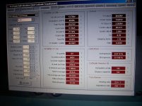
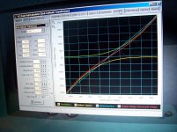
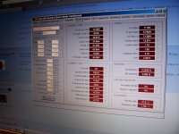
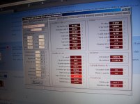
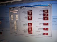
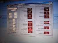
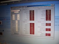
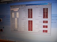
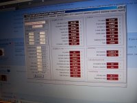
I tried redoing the sims. The only way I could get my sim to come close to yours was to increase the transformer load to 14.1k. I took a few screen shots, let's see if I can post them.
Check out the distortion on the last simulation.
 What's the catch? Look at the required drive voltage.
BTW, 22 years ago, before I knew 1/10th the pittance I know now, I built an EL34 amp. Still works today, only thing ever failed is the power switch. Used Joe Curcio's input circuit from Glass Audio. It is switchable between pentode and triode. 30mA bias current and 440V on the plates. Measured about 26 watts at visible clipping in triode, 42 watts in pentode using a 375 volt regulated supply. So, I suspect my numbers may be close. Used outputs from a Fisher 500C receiver.
Stuart
Attachments
-
 100_3046.jpg693.1 KB · Views: 161
 -
 100_3047.jpg528.2 KB · Views: 157
 -
 100_3055.JPG845.8 KB · Views: 149
 -
 100_3059.jpg562 KB · Views: 23
 -
 100_3058.jpg551.3 KB · Views: 137
 -
 100_3056.jpg587.6 KB · Views: 140
 -
 100_3061.jpg541.1 KB · Views: 21
 -
 100_3063.JPG721.2 KB · Views: 20
 -
 100_3064.JPG893.7 KB · Views: 26
Last edited:
- Status
- This old topic is closed. If you want to reopen this topic, contact a moderator using the "Report Post" button.
- Home
- Amplifiers
- Tubes / Valves
- Noob. Help PP EL34 / EF86 both as triode schem.