They only had SMD parts ")
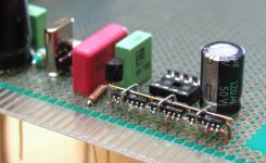
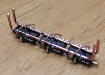
Here's my reclocker circuit. The 3 dual flip-flops were available only as SMD parts so I had to figure out how to make it nicely with p2p. They are mounted on 2 rails out of copper wire, which are also actual voltage rails. The jumpers on top and piece of wire is clock connection. After doing it this way, I'm actually glad they didn't have through the hole components. It takes much less space and looks great
Here's my reclocker circuit. The 3 dual flip-flops were available only as SMD parts so I had to figure out how to make it nicely with p2p. They are mounted on 2 rails out of copper wire, which are also actual voltage rails. The jumpers on top and piece of wire is clock connection. After doing it this way, I'm actually glad they didn't have through the hole components. It takes much less space and looks great
Attachments
Dear audiophilic friends,
I am wondering. Could anybody be so friendly to try once 'my' Nonoz II DAC configuration. So with 2x1.5 K, 1 K and 8V supply (7808).

Sorry, if I may seem to beggin for some attention. I am just wondering what you think of this configuration compared to the 3x1k, 5V configuration
Muchos regards,
Fedde
I am wondering. Could anybody be so friendly to try once 'my' Nonoz II DAC configuration. So with 2x1.5 K, 1 K and 8V supply (7808).
Sorry, if I may seem to beggin for some attention. I am just wondering what you think of this configuration compared to the 3x1k, 5V configuration
Muchos regards,
Fedde
Well, I had some experiments again this evening. I renovated my previous DAC (I had stripped aways some components before). I included a 5V supply and the famous 3x1k configuration (with standard carbon resistors). The output capacitors are blue 2.2 uF MKT cubes. There is no input transformer, no extra 12V regulator, no toroid (I use an old commodore 16 supply with a cheapo bridge inside) and no funky case (and no reclocking).
So the DAC is quite different from the Nonoz II DAC. I compared them a few times this evening. The Nonoz II DAC seems to be more accurate and dynamic, but also more tiring. The stereoplacement of the Nonoz II is worse, maybe due to the 3.3 nF capacitor still inside that filters a little 15-20kHz away. The old DAC with 5V is more relaxing, it filters some information away but is maybe more musical, listenable and enjoyable. This asks for more research...
My motivation for using 8V was increased dynamics and tighter bass (and higher output). My gainclone in previous condition needed that to be listenable (not too wooly). I did some mods to my gainclone that made it faster & more dynamic. Maybe now 5V is a better compromise. Well, it could be that 6V is the best compromise. But then I have to change the Vref resistors slightly for an optimal setting. Even with 5V, 3x1k is not optima. The rest point is now at 3.0 V, where it should be at 2.8V ! (in the middle between 1.8V and Vsupply-1.2V=3.8V)
Well, I have to do some more experiments!!!
Fedde
I never liked the idea of multiple DAC chips very much. You always get differences between chips due to digital timing and analog circuit fabrication differences.
But using a higher voltage is something different. Scott Nixon is still an advocate of higher voltages (based on his website).
It's essential that the correct resistors are used when higher voltages are used.
I am not 100% sure that the difference in voltage is the reason that I seem to prefer the older DAC, but I suspect that. Some further testing will answer these questions.
Regarding the rest point, I already gave a hint in my previous post (and more clearly in my previous mail to you )
The operating window of the TDA1543 is from 1.8 V to the supply-1.2V. So in the case of 5V supply this is from 1.8 V to 3.8 V. The rest point should IMHO be in the middle between these borders, so at 2.8 V. This is the voltage across the capacitor (or at the output).
Fedde
But using a higher voltage is something different. Scott Nixon is still an advocate of higher voltages (based on his website).
It's essential that the correct resistors are used when higher voltages are used.
I am not 100% sure that the difference in voltage is the reason that I seem to prefer the older DAC, but I suspect that. Some further testing will answer these questions.
Regarding the rest point, I already gave a hint in my previous post (and more clearly in my previous mail to you
)The operating window of the TDA1543 is from 1.8 V to the supply-1.2V. So in the case of 5V supply this is from 1.8 V to 3.8 V. The rest point should IMHO be in the middle between these borders, so at 2.8 V. This is the voltage across the capacitor (or at the output).
Fedde
Re: They only had SMD parts
Hi Peter,
Be sure to add some local supply decoupling caps to the MC74VHC74's unless your name is Ricardo/NE5534 rules!

Peter Daniel said:Here's my reclocker circuit. The 3 dual flip-flops were available only as SMD parts so I had to figure out how to make it nicely with p2p. They are mounted on 2 rails out of copper wire, which are also actual voltage rails. The jumpers on top and piece of wire is clock connection. After doing it this way, I'm actually glad they didn't have through the hole components. It takes much less space and looks great
Hi Peter,
Be sure to add some local supply decoupling caps to the MC74VHC74's unless your name is Ricardo/NE5534 rules!
Interested
Hi,
Peter.. I have always read your posts and find them very informative.
Wondering if you have a link to your non-os DAC with the single TDA1543 DAC?
I believe you said that the receiver circuitry and PS were pretty much taken from a schematic by Kusoniki? I probably spelt that wrong.
I want to use the 5v supply but run both the receiver and DAC from 6V SLA batteries.... do you recommend the same filtering on the PS for this?
Thanks!!!
Re: Interested
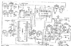
I guess JP is already tired with sending all those e-mails and schematics, so here is the 3rd Kusunoki DAC. That's the best copy i have
RichardJones said:
Wondering if you have a link to your non-os DAC with the single TDA1543 DAC?
I guess JP is already tired with sending all those e-mails and schematics, so here is the 3rd Kusunoki DAC. That's the best copy i have
Attachments
Thanks!!!
Is this schematic the same as this DAC:
http://www.diyaudio.com/forums/showthread.php?postid=168546#post168546
?
Thanks!!!!
Is this schematic the same as this DAC:
http://www.diyaudio.com/forums/showthread.php?postid=168546#post168546
?
Thanks!!!!
jean-paul said:I think there is a copyright on it from MJ magazine that forbids to publish it. Not sure about it but it is better to be careful with such matters.
You are sure right I am tired of mailing !
I couldn't see the copyright note anywhere on the drawing. It may be because of poor copy quality or because it is in Japanese
I've seen the first schematic on the net and it was also reprint from MJ magazine and nobody complained about copyrights, so... lets's enjoy it while we can, somebody else might decide to remove it from here.Re: Thanks!!!
It is not the same. The only part I took from 3rd schematic is DAC setup (and this also not exactly). I like passive filtering of a first one and simple regulators for receiver and DAC.
When using batteries, you don't need passive filtering, just regulator from 6.5V down to 5V.
RichardJones said:Is this schematic the same as this DAC:
http://www.diyaudio.com/forums/showthread.php?postid=168546#post168546
?
Thanks!!!!
It is not the same. The only part I took from 3rd schematic is DAC setup (and this also not exactly). I like passive filtering of a first one and simple regulators for receiver and DAC.
When using batteries, you don't need passive filtering, just regulator from 6.5V down to 5V.
regulators and original DAC setup?
I assume then I need low dropout regulators? Any recommendations?
Do you have a schematic for the first DAC?
How much is the current draw of the receiver chip and DAC ? That way I can determine how to do the PS.
Seperate batteries and regulators for receiver digital and analog and DAC? So 3 supplies?
No bypass caps on the batteries, other than what the regulator needs?
Thank you!!!!!!
The first one is here: http://www.homestead.com/whaan/files/tda1543_dac.jpg
As to PS, I'm still experimenting and the best approach is trial and error. The current draw is about 30mA for digital section of receiver, 60mA for analog section and 50mA for DAC.
As to PS, I'm still experimenting and the best approach is trial and error. The current draw is about 30mA for digital section of receiver, 60mA for analog section and 50mA for DAC.
And to make the info package complete, here's the interview with Mr. Kusunoki from TNT magazine: http://www.tnt-audio.com/intervis/kusunoki_e.html
- Status
- This old topic is closed. If you want to reopen this topic, contact a moderator using the "Report Post" button.
- Home
- Source & Line
- Digital Source
- Non Oversampling DAC-complementing CD-PRO