there is a group buy for the calvin buffer , Calvin is a very talented designer , and his buffer seems perfect for your application.
I am also doing a buffer for my headphones , but I have a lot of projects going on right now , so it is on hold .
http://www.diyaudio.com/forums/group-buys/239776-calvin-buffer-paradise.html
What is so special about that buffer ?? Its just another old and tried concept as is the diamond. The diamond works as well, in fact I suspect it outperrforms it and is simpler in design.
Manso, can you show me a new buffer concept , I am always looking for new solutions.
And the buffer concept in #140 is also a old and tried concept ? what is the freshness level in a scale of 1 to 10 ?
Thanks very much for all the information you can give me in this important matter.
And the buffer concept in #140 is also a old and tried concept ? what is the freshness level in a scale of 1 to 10 ?
Thanks very much for all the information you can give me in this important matter.
Ok. now serious. Manso, can you show me a link from a buffer concept that you think is better than those that we discuss.
No this is the reason I asked why the importance of the calvin buffer which is no better than a diamond and in actual fact worse. For what possible reason would I want to change to a lesser performing circuit than what I already use ?? For the sake of it being different, not my glass of wine sorry. Perhaps in that case maybe we should start using a one Mosfet buffer with 1000 times worse performance.
The design as shown is excellent, nothing needs to be changed or improved with regards to the buffer, indeed can it ?? Well maybe your error correction buffer but as you are not showing it there is no point.
The use of ONDF was a master stroke, not only can it further improve THD performance but it also acts as Servo. Dadod went as far that you can choose whether to use this feature or not as well as the use of discrete circuit opamps for the ONDF.
What else could one hope for, a circuit to worsen performance perhaps ??
sometimes I don't know why I bother...
good luck .
Youre overly sensitive to valid queries.
Rather you should state why calvin buffer is better suited to the application. If it does bring any benefits show them. Note a objective reason is not neccesarily the view of others but there is no problem if you go ahead and rather use the calvin for yourself. I think damir has already extended himself in effort, allowed and designed many options to perspective builders requests, none so far detrimental. To ask for a lesser circuit to be implemented without validation is unreasonable.
Manso , I think both buffers are technically ok, I never heard none of them , but I use buffers with the same topology than the one that Damir use, so I know the strong points and limitations of the topology. And ofcourse if I use them is because i like them.
I never heard the Calvin buffer , the only thing I said , is that joachim G. have tested and heard them , and people are saying good things about it.
The Calvin buffer use local feedback , and some nice tricks.
I just suggested the Calvin buffer because I thought that Damir was not happy with the performance of his buffer , it was a misunderstanding .
Another thing. All my sound components use global feedback , and my amplifier use feedback and hec error correction, except the DAC´s that are non feedback ,
I think feedback is a good technique , and I have good results with it. But I want to try to use non global feedback in other components like amplifiers and preamplifiers, preamplifier is not a priority , so I check sometimes what Damir is Doing, and I was somewhat disappointed to see that he was using global feedback , and the worst is that the implementation is not good , the feedback loop is too slow .
but ofcourse you guys are free to experience the topologies that you want, and is even possible that I am wrong (I am wrong lots of times) , and you have discover at last the perfect audio circuit.
Tchau
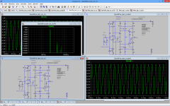
Today, I have simulating the Damire gainwire circuit without the buffer and the opamp , and it gave incredible low distortion values (0.000033%). so I change all the cordell models with nxp spice model, and the distortion was also low (0.00044%) mainly 2º harmonic.
That is a problem that I have, the NXP models give more distortion than in reality because of the early voltage distortion, and the Cordel models give lower than in reality, but the NXP models give results closer to reality.
One way or another, this is a very good value.
Congratulations Damire
That is a problem that I have, the NXP models give more distortion than in reality because of the early voltage distortion, and the Cordel models give lower than in reality, but the NXP models give results closer to reality.
One way or another, this is a very good value.
Congratulations Damire
Attachments
Today, I have simulating the Damire gainwire circuit without the buffer and the opamp , and it gave incredible low distortion values (0.000033%). so I change all the cordell models with nxp spice model, and the distortion was also low (0.00044%) mainly 2º harmonic.
That is a problem that I have, the NXP models give more distortion than in reality because of the early voltage distortion, and the Cordel models give lower than in reality, but the NXP models give results closer to reality.
One way or another, this is a very good value.
Congratulations Damire
Thanks smms73,
Yes the gain stage has very low distortion and the main problem for me was to find a buffer good enough not to spoil it. If you followed the thread from the begining I showed that. And I think that the buffer I am using is good enough.
BR Damir
Yes , Damir , I also agree , the buffer that you use are good enought .
I would like to show you a way to use your circuit to control the output d.c. without the opamp, let me just take a picture.
Sergio you showed before very nice circuits and if you permit me I would use some part in my future design.
And I wait for your solution for the output DC control.
BR Damir
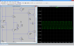
Ok the change is simple, you only need to add a resistor and a capacitor to the resistor r9 , in this case the output D.C was -24mv without the change , and is now -600uV . Test it , have to do more tests , but it seems a good solution.
Attachments
Last edited:
Ok the change is simple, you only need to add a resistor and a capacitor to the resistor r9 , in this case the output D.C was -24mv without the change , and is now -600uV . Test it , have to do more tests , but it seems a good solution.
It works, much less DC offset but still 3.7mV. I'll try tomorrow more tests, thenks Sergio.
BR Damir
Electrolytic caps can produce distortion , but that is just audible and measurable when there is a significant amount of A.C. voltage at the cap terminals , for exemple in a speakers crossover or filters, electrolytics in crossovers is a very bad idea because the amount of A.C. voltage at the terminals of the cap can be large enought to produce audible amounts of distortion (although it is mainly 2º and 3º harmonics ) .
In this case we want to shunt all the audible frequencies to ground , so the A.C. voltage at the cap terminals is so low that the distortion produced by the cap will be negligible.
The elna silmic II bipolar is a very good capacitor for this position.
The larger the capacitor the better , a 470uf cap can be a better choice.
A output coupling capacitor is also neded in this type of circuits , and my advice is using a large polipropilene capacitor (larger than 10uF) for the same reason, to have low A.C. voltage at the cap terminals .
using a coupling capacitor is better than to use a dc servo , for several reasons.
first the opamp from the servo will produce noise ,
the distortion from the opamp alone is probably higher to that of the capacitor,
and the dc-servo also has capacitors that also produce distortion that will be injected in the signal path.
And at last the most important , the coupling capacitor has a protective effect and that is really very important.
Cyril Bateman has some very informative articles published on Electronics World about capacitor distortion. If you want to know more about capacitors , google "measuring capacitors distortion bateman"
Last edited:
Electrolytic caps can produce distortion , but that is just audible and measurable when there is a significant amount of A.C. voltage at the cap terminals , for exemple in a speakers crossover or filters, electrolytics in crossovers is a very bad idea because the amount of A.C. voltage at the terminals of the cap can be large enought to produce audible amounts of distortion (although it is mainly 2º and 3º harmonics ) .
In this case we want to shunt all the audible frequencies to ground , so the A.C. voltage at the cap terminals is so low that the distortion produced by the cap will be negligible.
The elna silmic II bipolar is a very good capacitor for this position.
The larger the capacitor the better , a 470uf cap can be a better choice.
A output coupling capacitor is also neded in this type of circuits , and my advice is using a large polipropilene capacitor (larger than 10uF) for the same reason, to have low A.C. voltage at the cap terminals .
using a coupling capacitor is better than to use a dc servo , for several reasons.
first the opamp from the servo will produce noise ,
the distortion from the opamp alone is probably higher to that of the capacitor,
and the dc-servo also has capacitors that also produce distortion that will be injected in the signal path.
And at last the most important , the coupling capacitor has a protective effect and that is really very important.
Cyril Bateman has some very informative articles published on Electronics World about capacitor distortion. If you want to know more about capacitors , google "measuring capacitors distortion bateman"
Yes I know all that abouth distortion in capacitors, I've read that Cyril Bateman article and I have EW (I was buying EW before it vent to crap).
Thanks Damir
I have made a temperature sweep from 0º to 50º and the alteration have manage to compensate the temp. variation, except for the input stage, 13mv.
ofcourse a sub mv variation is only possible with a dc-servo.
You should also check the ccs at input, the bias current changed from 4.5ma to 3.8ma with the temp. variation, I recomend another type of ccs.
ofcourse a sub mv variation is only possible with a dc-servo.
You should also check the ccs at input, the bias current changed from 4.5ma to 3.8ma with the temp. variation, I recomend another type of ccs.
- Status
- This old topic is closed. If you want to reopen this topic, contact a moderator using the "Report Post" button.
- Home
- Amplifiers
- Solid State
- No NFB line amp (GainWire mk2)