Hi!
I would like to ask some questions about the PSU:
For only one channel (in a dual mono amplifier)
- how big transformers need I? For the power tubes 250VA? For 6C33C heater 100VA and for the driving tubes 15VA enough?
- should the R33 1K be 5W?
- should the FS1 and FS2 fuses be 1.5A?
- instead of the amp meters 0.1Ohm power resistor"s wattage?
Greets:
Tyimo
Yes, since the PSU details in the Tim Mellow article are for the case that it supplies power for two amplifiers (i.e. stereo), then if you are going to make monoblocks, each with its own power supply, then you can essentially divide by two on the ratings for the various components you are asking about.
Chris
Thank you Chris and Rudolf!
One more question:
Should I use 1/2W trimmer insted of the 1W trimmer for RV2 and RV3? I can get only 1/2W type.
Greets:
Tyimo
I think you should be OK with 1/2W trimmers. The power dissipation in RV2 will be rather minimal, and the worst case dissipation in RV3 is about 1/10 W or so.
Chris
Do be sure to use multi-turn potentiometers for RV2 and RV3. It is extremely helpful for making the rather fine adjustments that are needed.Thank you very much!
Chris
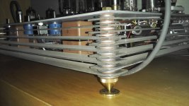
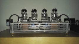
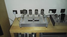
2 years on and amp is still Running great, hats off to Tim for his design,,
Only upgrade is the golf cone feet
( for looks only in my opinion )
Busy building a tda1543 NOS balanced output dac
intend to convert amp to balaced input with miniature xlr plugs
Only upgrade is the golf cone feet
( for looks only in my opinion )
Busy building a tda1543 NOS balanced output dac
intend to convert amp to balaced input with miniature xlr plugs
Attachments
2 years on and amp is still Running great, hats off to Tim for his design,,
Only upgrade is the golf cone feet
( for looks only in my opinion )
Busy building a tda1543 NOS balanced output dac
intend to convert amp to balaced input with miniature xlr plugs
Mine also has been running for two or three years now with no problem. A very reliable amplifier, and a great sound.
Chris
Bump...
Following the thread from the beginning ..all great stuff what would be very helpful if you guys would provide some information on where to get the inexpensive transformers, capacitors etc...most of the other parts can be gotten anywhere or in your parts box...
Personally interested in EI type for its inherent storage capabilities and its natural ability to not pass line hf noise (capacitance)
Thanks
Lawrence
Hi!
Could someone explain to me how that gas discharge tube works as a speaker protection?
Greets:
Tyimo
I don't think it is intended to protect the speaker. My guess is that it is simply there to ensure that under any worst-case fault conditions, and even with no speaker connected, the voltage on the "live" speaker output terminal cannot exceed 90V. Quoting from Tim Mellow's article "The gas discharge tube, N2, ensures that the output voltage is kept within safe limits under all conditions."
Chris
Bump...
Following the thread from the beginning ..all great stuff what would be very helpful if you guys would provide some information on where to get the inexpensive transformers, capacitors etc...most of the other parts can be gotten anywhere or in your parts box...
Personally interested in EI type for its inherent storage capabilities and its natural ability to not pass line hf noise (capacitance)
Thanks
Lawrence
I've opted for toroidal transformers in my more recent OTL amps, including the Tim Mellow amp. But previously, I've used Edcor transformers quite successfully.
The strings of series-connected electrolytics shown in the power supplpy schematic are really overly elaborate. I just used standard type 200V electrolytics from Mouser.
Chris
Last edited:
Thank you!"The gas discharge tube, N2, ensures that the output voltage is kept within safe limits under all conditions."
I've opted for toroidal transformers in my more recent OTL amps, including the Tim Mellow amp. But previously, I've used Edcor transformers quite successfully.
The strings of series-connected electrolytics shown in the power supplpy schematic are really overly elaborate. I just used standard type 200V electrolytics from Mouser.
Chris
Hi Chris. I'm not sure I understand how you are replacing the string of caps and resistors. Can you say more.
Hi Chris. I'm not sure I understand how you are replacing the string of caps and resistors. Can you say more.
He is connecting four 6800 uF capacitors, each rated at 63V, in series, which effectively makes a composite 1700 uF capacitor with a working voltage of about 250V. (Two of these composite capacitors in total; one for the B+ and one for the B-.) The 10K resistors across the capacitors are for balancing the voltage drops across the four capacitors. Instead. one can just use a single capacitor with a high enough working voltage (200V is OK), in place of each "composite capacitor," since it is easy enough to find high-capacity 200V electrolytics these days.
There is no need for any parallel resistor for balancing purposes any more. It's still a good idea to have one anyway, to provide a slow discharge of the capacitor when the power is turned off.
Chris
Last edited:
- Home
- Amplifiers
- Tubes / Valves
- New Tim Mellows OTL project