I try turn on both side in same time . The problem with current was just with one side another one work more stable . In the driver I use E83cc from Czech rep . First of all I thought about tube V2 V3 . I try swich both of them from another(stable side) but it seems no effect . The current rise up on this side. In the driver I use E83cc from Czech rep . After that I try swich of them on 6n2p but it seems problem still same.
I check voltage on check point. Just after turn on all voltage was very close like on schem. But after warming up I find misbalance in the +150 and -150 rails It was around -146 and +166 I do not remember exactly(I bild amp in my lab.) . I check voltage on trans output – its OK 115v on both. How you solve problem with +150 and -150 rails centered around the ground??? but the current rise just on one side .... another one work ok...
I check voltage on check point. Just after turn on all voltage was very close like on schem. But after warming up I find misbalance in the +150 and -150 rails It was around -146 and +166 I do not remember exactly(I bild amp in my lab.) . I check voltage on trans output – its OK 115v on both. How you solve problem with +150 and -150 rails centered around the ground??? but the current rise just on one side .... another one work ok...
Attachments
I try turn on both side in same time . The problem with current was just with one side another one work more stable . In the driver I use E83cc from Czech rep . First of all I thought about tube V2 V3 . I try swich both of them from another(stable side) but it seems no effect . The current rise up on this side. In the driver I use E83cc from Czech rep . After that I try swich of them on 6n2p but it seems problem still same.
I check voltage on check point. Just after turn on all voltage was very close like on schem. But after warming up I find misbalance in the +150 and -150 rails It was around -146 and +166 I do not remember exactly(I bild amp in my lab.) . I check voltage on trans output – its OK 115v on both. How you solve problem with +150 and -150 rails centered around the ground??? but the current rise just on one side .... another one work ok...
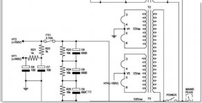
I have always had similar problems of an imbalance between the +ve and the -ve supply rail voltages if I follow precisely the power supply design in the Tim Mellow article. I solved it by shorting out the 1K ohm resistor R33, so that the centre tap of the power transformer is then connected directly to ground. The two supplies are then pretty well constrained to be the same voltages (+ and -). As I said in my post 116, I think there are definite advantages to configuring the power supplies like this (although I don't believe it achieves any reduction in impedance at audio frequencies, but that is a different discussion), especially from the point of view of stabilising the voltages on each half.
You could also try an intermediate measure, of shunting R33 with a much lower value resistor.
Chris
Yes with the centre tap connected direct to the capacitors without any resistor you will not have any imbalance between the +ve and the -ve supply
Personaly I don't build the Tim Mellows OTL but I build an OTL amplifier ( Futterman topology ) with 12 PL36 tubes in each channel since 2004 ( wich is completely my design ) with the CT directly connected to the capacitors and I never have any impalance issue and it's working fine without any problem till now , maby Tim Mellow amp designed like that for saftey reasons or other reasons .
And for the history I have to say that maby cnpope connected the CT directly to the capacitors after the discussion we had in this thread with him getting started from my post #90 .
Thanks Dimitris .
Yes with the centre tap connected direct to the capacitors without any resistor you will not have any imbalance between the +ve and the -ve supply
Personaly I don't build the Tim Mellows OTL but I build an OTL amplifier ( Futterman topology ) with 12 PL36 tubes in each channel since 2004 ( wich is completely my design ) with the CT directly connected to the capacitors and I never have any impalance issue and it's working fine without any problem till now , maby Tim Mellow amp designed like that for saftey reasons or other reasons .
And for the history I have to say that maby cnpope connected the CT directly to the capacitors after the discussion we had in this thread with him getting started from my post #90 .
Thanks Dimitris .
Actually no. When I first built the Tim Mellow amp almost 2 years ago, I tried following his schematic with the R33 1K ohm resistor in place, and quickly found that it led to major imbalance on the two supply rails, so I shorted it out and fixed the problem. Just recently, a couple of months ago, I tried experimenting again with introducing R33 (but with a much lower value than in Tim Mellow's schematic--about 80 Ohms or so). There is still a significant imbalance, so next time I heat up the soldering iron I'm going to revert to a direct grounding of the centre tap. (But not for any any audio frequency impedance-reduction purposes!
") )
)Chris
Last edited:
OK cnpope it's clear now .Actually no. When I first built the Tim Mellow amp almost 2 years ago, I tried following his schematic with the R33 1K ohm resistor in place, and quickly found that it led to major imbalance on the two supply rails, so I shorted it out and fixed the problem. Just recently, a couple of months ago, I tried experimenting again with introducing R33 (but with a much lower value than in Tim Mellow's schematic--about 80 Ohms or so). There is still a significant imbalance, so next time I heat up the soldering iron I'm going to revert to a direct grounding of the centre tap. (But not for any any audio frequency impedance-reduction purposes!
Chris
Hi,
Just my observation on the 'h.t imbalance' thread. I mentioned a while ago that due to using non centre tapped transformers for the + & - rails, adding a volt meter greatly aids the easy balancing of the two rails (+ & - 165v in my case)(same with the 6C33 & 6C41 versions) I would only add that these two amps have been in regular use for around 18months with very little drifting - but - there is (on both amps) - at the speaker terminals an offset of around 30mV dc which is positive wrt chassis on one channel and negative on the other) this seems to be a function of the design. One stereo channel always settles to it's correct idle current before the other (both amps). I have also noticed that when setting balance and standing current, that if one channel is 'backed off' i.e, 6C33C's biased off - adjusting the balance of that channel will effect the balance of the other channel - which is unexpected, but probably due to the sharing of ht supplies by both channels. I believe that using seperate ht supplies would cure this problem, although as it's a minor niggle I probably won't bother (!)
Anyone else confirm (or otherwise) these observations please?
Regards,
David.
cnpope,
Just for interest..looking at the Tim Mellow..two clips..
Regards
M. Gregg
Yes, indeed. The design by Tim Mellow is probably a good one for nulling out any power supply ripple. If I get the time this weekend, I'll try to get some quantitative measurements of the hum level on the output, and the ripple voltage on the supply rails. It could be interesting to compare with other designs.
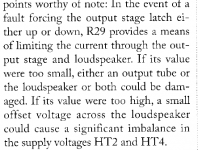
And yes, I felt a considerable nervousness at first, when I shorted out R33 (inadvertently called R29 in the text of Tim's article), precisely because it then means that a fault in either the upper or the lower output stage could have potentially catastrophic consequences. Two years on and I've not had any trouble, so I've more or less stopped worrying about it. Hopefully, the fuses will take care of any fault-induced surges. The security one would achieve by including R33 comes at the price of the tendency of the supplies to go out of balance, so I suppose one just has to make one's own choice of risk vs benefit.
Chris
Hi everyone !
Thanks Chris ! I connect ground point with common point of transformers and solve problem with imbalance of power supply. The current stay more stable .
And finaly I can not adjust zero on one side. ... It still 200 mv even then I full rotate RV2 to one side ?? On another side all OK May be it no big deal .....Sounds good even in this case
Thanks all
Hi everyone !
Thanks Chris ! I connect ground point with common point of transformers and solve problem with imbalance of power supply. The current stay more stable .
And finaly I can not adjust zero on one side. ... It still 200 mv even then I full rotate RV2 to one side ?? On another side all OK May be it no big deal .....Sounds good even in this case
Thanks all
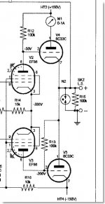
I would suggest that on the side with the 200 mV imbalance, you try swapping the two 6C33C tubes, and see whether that changes the sign of the imbalance voltage. If that doesn't do it, then try swapping the two EF86 tubes, and see if that changes anything. If not, then try a different ECC83 input tube. If none of those alters the sign of the imbalance, then there must probably be something imblanced in the circuitry. Assuming no wiring errors, then maybe an out off spec resistor? But much more likely, I suspect, is that it's something to do with imbalanced tubes, which should be revealed by the swapping suggested above.
Chris
As I said before in post #123 '' for saftey reasons'' and I mean that , using high gm / high current tubes like 6C33C there is more possibilities to destroy the loudspeakers if the CT is connected , so BE CAREFULL it's better to use protection circuit for the loudspeakers when you connect the CT .maby Tim Mellow amp designed like that for saftey reasons or other reasons .
Thanks Dimitris .
Last edited:
Hi every one !
Chris
"you try swapping the two 6C33C tubes, and see whether that changes the sign of the imbalance voltage."
I try swapping two 6C33C tubes but sign of the imbalance voltage same. Before i change all anothe tubes. So it seems some thing with value resistors .(actually i am not use precision stuff, )
Thanks for attention about loudspeakers Dimitris .
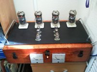
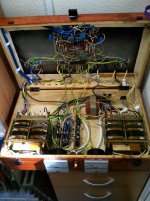
About Hum. Actually then I bild this type disine of body I am waiting for some Hum . But surprisely nothing scary. The trans plased not directly under tube . And quality the trans good(500 va each , grounding wire etc...no noisy ). I got them from poland CAMAK systems
Chris
"you try swapping the two 6C33C tubes, and see whether that changes the sign of the imbalance voltage."
I try swapping two 6C33C tubes but sign of the imbalance voltage same. Before i change all anothe tubes. So it seems some thing with value resistors .(actually i am not use precision stuff, )
Thanks for attention about loudspeakers Dimitris .
About Hum. Actually then I bild this type disine of body I am waiting for some Hum . But surprisely nothing scary. The trans plased not directly under tube . And quality the trans good(500 va each , grounding wire etc...no noisy ). I got them from poland CAMAK systems
Hi every one !
Just remind: it was problem with zeroo reg. on one side my OTL
I check value resistors R8 R9 it was not correct 4,8 m (more) I change both of them and now zerro ok.
Thanks all
Glad to hear you solved the imbalance problem!
I made a few measurements this last weekend, to try to estimate the hum level. On my Hans Beijner OTL, which is a bit lacking in smoothing capacity on the main supplies, I measured a ripple of about 1.25V peak to trough. On the output to the speaker, this was leading to about 12mV mains ripple.
On my Tim Mellow OTL amp, I have about 0.5V peak to trough ripple on the B+ and B_- supplies to the output tubes. There was no detectable ripple signal on the speaker outputs, even on the 2mV/div scale on the oscilloscope. So hum on the output, which was inaudible by listening on the speakers, is indeed unmeasurable on the scope also.
My conclusion is that the simplest of power supplies, provided that the capacitors are reasonably big (4,400uF in my Tim Mellow amp), is more than adequate. Hum is simply not an issue.
Chris
Hi All, I have been following this and the other Tim Mellow threads. I have collecting parts for some time now and have a question. I have all the bits to make a tube rectifed CLCLC power supply and was wondering if an OTL or Tim's design in particular needs the PS he developed. Is there anything special about his PS that a tube rec supply could or would not do? TKS. D.
Hi All, I have been following this and the other Tim Mellow threads. I have collecting parts for some time now and have a question. I have all the bits to make a tube rectifed CLCLC power supply and was wondering if an OTL or Tim's design in particular needs the PS he developed. Is there anything special about his PS that a tube rec supply could or would not do? TKS. D.
I think,
You are over looking the Bias supply created by the Tim Mellow PSU..also the values of chokes are critical in an OTL PSU..eg the dc resistance will create sag..also the bass current will be limited..The amount of "L" in most OTLs I have seen are 2H at 0.5 Ohm...I have varied this value...and it does make a difference.
Regards
M. Gregg
- Home
- Amplifiers
- Tubes / Valves
- New Tim Mellows OTL project