.
By the way, I am a great fan of OTL amps, and have built three of them, using the designs of Hans Beijner, Tim Mellow and Alan Kimmel.
Chris
Which one is your favorite amp and why?
")
Just for interest the CT of the power supply has a big impact on the sound of the amp and also any values of series resistance such as R33 used in the Tim Mellow. It seems to "shift" the frequency response that is heard. I never tested this but it is easy to hear. Not like is this cap better than that cap. The bass changes. This may be to do with damping factor and speaker control of the OP stage.
Only my opinion, I think the power supply used in most of the OTL's is over simplified and more attention should have been spent on the design. IT seems to be one of the highest complaints on the web.
Regards
M. Gregg
Last edited:
Which one is your favorite amp and why?
Just for interest the CT of the power supply has a big impact on the sound of the amp and also any values of series resistance such as R33 used in the Tim Mellow. It seems to "shift" the frequency response that is heard. I never tested this but it is easy to hear. Not like is this cap better than that cap. The bass changes. This may be to do with damping factor and speaker control of the OP stage.
Only my opinion, I think the power supply used in most of the OTL's is over simplified and more attention should have been spent on the design. IT seems to be one of the highest complaints on the web.
Regards
M. Gregg
I think probably I like the Tim Mellow amp the best. It seems to be the most stable (in the sense of the output offset drifting the least, and the quiescent current through the output tubes staying steady). Possibly my implementation of the Hans Beijner design is a bit flawed, with the transformers, capacitors, etc. of the bias supplies getting rather too hot because of proximity to a slightly inadequate heater transformer for the 6C33Cs, and that might explain the tendency of the HB amp to drift a bit more.
When I built the Tim Mellow amp I was uneasy with the imbalance between the positive and negative main supply rail voltages, and so i just shorted out R33 (meaning the centre-tap of the transformer is connected to ground). More recently, I tried reintroducing an R33, but with a much lower value than in Tim Mellow's schematic (82 ohms rather than 1K). I can't say I noticed any difference in the sound, but I have to admit that my ears seem not to be very good at picking up the differences that others apparently can hear. I would tend to believe measurements more than my own ears, I think! I will try making a few comparative measurements.
It is, by the way, interesting if you do have a resistor between the centre-tap and ground to try putting a scope on the centre-tap. The crud that one sees there is quite something!
It is true that the power supply is typically less than ideal. With 2000 uF capacitors, there is something of order 1.5V "ripple" (in line with what is expected from I = C dV/dt) even under quiescent conditions. But things must balance out pretty well, because even with my ear next to my 98dB Lowthers, hum is essentially inaudible.
Chris
It is good that we agreed on something that is a given , I mean about the power supply , and it would be nice if we saw one of your creations on the forum .I think then we are in complete agreement; there is more to a power supply than just the audio signal path. My previous comments were specifically addressing the restricted question of the audio path, and I was pointing out that regardless of the centre-tap connection or not, the capacitors are part of the audio signal path.
By the way, I am a great fan of OTL amps, and have built three of them, using the designs of Hans Beijner, Tim Mellow and Alan Kimmel.
Chris
As for the CT , Ιt is a part of the power supply and if it's connected ( to the capacitors and to earth of course ) the amp will have lower output impedance and therefore higher damping factor , this happens because with this way the capacitors are not in series with the output tubes ( like output capacitors ) and the speaker but they are in parallel with these ( the power supply capacitors are always in parallel with the output stage and the speakers ) .
Your own words Evidenced that the CT is a part of the power supply and a very important one , I wonder how you don't see that .When I built the Tim Mellow amp I was uneasy with the imbalance between the positive and negative main supply rail voltages, and so i just shorted out R33 (meaning the centre-tap of the transformer is connected to ground). More recently, I tried reintroducing an R33, but with a much lower value than in Tim Mellow's schematic (82 ohms rather than 1K).
It is, by the way, interesting if you do have a resistor between the centre-tap and ground to try putting a scope on the centre-tap. The crud that one sees there is quite something!
Chris
Αnd if you put an oscilloscope on the edges of R33 ( CT and earth ) you will see a waveform exactly similar to the audio output signal but certainly on a smaller scale , this mean that this resistance increases the impedance of the power supply ( because it is inserted between the secondary windings and the power supply capacitors ) and thus increases the output impedance of the amp .
Your own words Evidenced that the CT is a part of the power supply and a very important one , I wonder how you don't see that .
Αnd if you put an oscilloscope on the edges of R33 ( CT and earth ) you will see a waveform exactly similar to the audio output signal but certainly on a smaller scale , this mean that this resistance increases the impedance of the power supply ( because it is inserted between the secondary windings and the power supply capacitors ) and thus increases the output impedance of the amp .
No, actually the waveform on the CT is rather horrific; not at all like the audio output. That is the most striking feature. It is dominated by a pulse related to the mains frequency. When I get the chance, maybe next weekend, I will try measuring the output impedance with the centre-tap connected and with it not connected. But since Tim Mellow reports about 0.4 ohm output impedence with a 1Kohm resistor for R33, and I measured about 0.3 ohm output impedance with a direct short circuit in place of R33, then I suspect that within experimental error/difference between his amp and mine, there is essentially no perceptible change from connecting the centre-tap or not. I don't think the calculated value of the output impedance is affected in any significant way by the connection of the centre tap.
Chris
No, actually the waveform on the CT is rather horrific; not at all like the audio output. That is the most striking feature. It is dominated by a pulse related to the mains frequency.
Chris
I have not measured,
However I guess these are the charge pulses to each side of the supply to caps via the diode bridge. So without the CT the caps charge across the +/- as one supply ie 300V. With CT each side charges as a seperate supply via half of the bridge.
Theoretically the charge cycle is dependant on ESR of supply caps or balance resistors for charge without CT.
Regards
M. Gregg
All that you say I've said in previous post ( post #92 e.t.c ) with different words , it would be better to read all the posts before and then subscribe , there is no need to say the same thing twice .However I guess these are the charge pulses to each side of the supply to caps via the diode bridge. So without the CT the caps charge across the +/- as one supply ie 300V. With CT each side charges as a seperate supply via half of the bridge.
Theoretically the charge cycle is dependant on ESR of supply caps or balance resistors for charge without CT.
Regards
M. Gregg
I have not measured,
However I guess these are the charge pulses to each side of the supply to caps via the diode bridge. So without the CT the caps charge across the +/- as one supply ie 300V. With CT each side charges as a seperate supply via half of the bridge.
Theoretically the charge cycle is dependant on ESR of supply caps or balance resistors for charge without CT.
Regards
M. Gregg
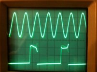
Yes, absolutely. Here are two photos showing what I am talking about. In the first photo, the upper trace is the audio output signal, and the lower trace is the signal on the centre-tap of the transformer (with 82 ohm resistor to ground). Both are 2V/div. There is no sign of the audio signal on the transformer centre-tap.
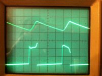
In the second photo, the upper trace is showing the voltage on the +160V line, showing how it decays (by about 1.3V) during each half cycle of the mains frequency, and then rapidly recharges. The lower trace is again the voltage on the transformer centre tap, illustrating how the ugly pulse correlates with the recharging phase.
Chris
Attachments
Yes, absolutely. Here are two photos showing what I am talking about. In the first photo, the upper trace is the audio output signal, and the lower trace is the signal on the centre-tap of the transformer (with 82 ohm resistor to ground). Both are 2V/div. There is no sign of the audio signal on the transformer centre-tap.
In the second photo, the upper trace is showing the voltage on the +160V line, showing how it decays (by about 1.3V) during each half cycle of the mains frequency, and then rapidly recharges. The lower trace is again the voltage on the transformer centre tap, illustrating how the ugly pulse correlates with the recharging phase.
Chris
Very interesting,
It would be interesting to see a trace of center point of caps with and without CT. Then a duel trace of CT connected each side of R33.
The traces you show don't even show a significant modulation from the audio out which would seem to say that the caps are in circuit for both situations, this would not account for the change in sound...except that the charge pulse " is ?" present at the cap Center point?
Regards
M. Gregg
Last edited:
Very interesting,
It would be interesting to see a trace of center point of caps with and without CT. Then a duel trace of CT connected each side of R33.
The traces you show don't even show a significant modulation from the audio out which would seem to say that the caps are in circuit for both situations, this would not account for the change in sound...except that the charge pulse " is ?" present at the cap Center point?
Regards
M. Gregg
Yes, the power supply capacitors are in the signal path equally much in either case. Also, it is obvious that there must be a "flatlining" of the signal on the centre tap for most of the mains frequency cycle (as is very clear in the traces), since for most of the mains cycle the output voltage from the power transformer is less than the DC voltages across the capacitors, the rectifier diodes are then completely non-conducting, and so the "hot" ends of the power transformer secondary are effectively completely isolated. Clearly, therefore, no current can flow out from the centre-tap during the majority of the mains cycle. This is one way to see why the centre-tap cannot possibly have a clean copy of the audio signal on it.
By the way, I suspect that the reason why in my traces the signal on the centre tap is a definite upward pulse is because of an imbalance between the capacitance of the B+ capacitors and the capacitance of the B- capacitors. (Electrolytic capacitors are notoriously imprecise in their tolerances.) I'll try to check this when I get the chance. I suspect that if I add a bit more capacitance to the one that is at present smaller, then the height of the pulse should reduce, and it should be possible to make it become instead a negative pulse if enough capacitance is added. If this is right, then it would seem that if one is going to have a non-zero R33 then it would be good to "pad" the smaller capacity bank so as to balance it with the other bank. I'll report back after I get the chance to check this.
It will be interesting to hear your conclusions,
It would be interesting to measure current if any from the CT..across R33. At idle and with drive.
Regards
M. Gregg
Last edited:
Yes, the power supply capacitors are in the signal path equally much in either case. Also, it is obvious that there must be a "flatlining" of the signal on the centre tap for most of the mains frequency cycle (as is very clear in the traces), since for most of the mains cycle the output voltage from the power transformer is less than the DC voltages across the capacitors, the rectifier diodes are then completely non-conducting, and so the "hot" ends of the power transformer secondary are effectively completely isolated. Clearly, therefore, no current can flow out from the centre-tap during the majority of the mains cycle. This is one way to see why the centre-tap cannot possibly have a clean copy of the audio signal on it.
By the way, I suspect that the reason why in my traces the signal on the centre tap is a definite upward pulse is because of an imbalance between the capacitance of the B+ capacitors and the capacitance of the B- capacitors. (Electrolytic capacitors are notoriously imprecise in their tolerances.) I'll try to check this when I get the chance. I suspect that if I add a bit more capacitance to the one that is at present smaller, then the height of the pulse should reduce, and it should be possible to make it become instead a negative pulse if enough capacitance is added. If this is right, then it would seem that if one is going to have a non-zero R33 then it would be good to "pad" the smaller capacity bank so as to balance it with the other bank. I'll report back after I get the chance to check this.
Seems now to be more likely the asymmetry (upward pulses on centre-tap rather than downward) might have a more mundane explanation; just an imbalance between the current draw on the upper and lower power supplies.
Chris
Last edited:
Yes, the power supply capacitors are in the signal path equally much in either case. Also, it is obvious that there must be a "flatlining" of the signal on the centre tap for most of the mains frequency cycle (as is very clear in the traces), since for most of the mains cycle the output voltage from the power transformer is less than the DC voltages across the capacitors, the rectifier diodes are then completely non-conducting, and so the "hot" ends of the power transformer secondary are effectively completely isolated. Clearly, therefore, no current can flow out from the centre-tap during the majority of the mains cycle. This is one way to see why the centre-tap cannot possibly have a clean copy of the audio signal on it.
By the way, I suspect that the reason why in my traces the signal on the centre tap is a definite upward pulse is because of an imbalance between the capacitance of the B+ capacitors and the capacitance of the B- capacitors. (Electrolytic capacitors are notoriously imprecise in their tolerances.) I'll try to check this when I get the chance. I suspect that if I add a bit more capacitance to the one that is at present smaller, then the height of the pulse should reduce, and it should be possible to make it become instead a negative pulse if enough capacitance is added. If this is right, then it would seem that if one is going to have a non-zero R33 then it would be good to "pad" the smaller capacity bank so as to balance it with the other bank. I'll report back after I get the chance to check this.
Very very nice, keep your misinformation , I will be watching with great interest
Very very nice, keep your misinformation , I will be watching with great interest
I have the feeling that this discussion is getting nowhere. Just to remind you:
In your message #90, you remarked that "I have built an OTL amp Futterman topology with 12 PL36 on each channel ( since 2004 ) and the center tap of the transformer is connected directly to the capacitors , with this way the capacitors aren't in the loudspeaker path because they are simply power supply capacitors ."
I responded, in #91, by pointing out that as far as the audio path is concerned, there is no essential difference between whether the centre-tap of the transformer is connected to ground or not. (Note that I explicitly emphasised that my discussion was specifically about the question of the audio signal path; it was not about any of the other pros and cons of grounding the centre-tap or not.)
In your message #104, you made the statement "Αnd if you put an oscilloscope on the edges of R33 ( CT and earth ) you will see a waveform exactly similar to the audio output signal but certainly on a smaller scale , this mean that this resistance increases the impedance of the power supply ( because it is inserted between the secondary windings and the power supply capacitors ) and thus increases the output impedance of the amp ."
I have shown the oscilloscope trace I get on th centre-tap in my message #108. As you can see, it does not look at all like a smaller scale version of the audio output signal. And, as I remarked in a follow-up message, it is very clear theoretically why the voltage on the centre-tap could not possibly look just like a smaller scale version of the audio output signal.
I therefore do not understand what your point is at this stage. Are you saying my scope trace of the centre-tap voltage is incorrect? Are you really wanting to say that the audio signal passes, in a significant way, through the power transformer and out through the centre tap if it is grounded?
I think it would be helpful if you gave a clear statement of what you believe the audio signal path to be in the case that the centre-tap is grounded.
Chris
Last edited:
IMHO that we can not speak about the signal path as an independed thing and not taken seriously into account the factors that create it ( output tubes , power supplies e.t.c. ) , and I am talking especialy about the power supply .I have the feeling that this discussion is getting nowhere. Just to remind you:
In your message #90, you remarked that "I have built an OTL amp Futterman topology with 12 PL36 on each channel ( since 2004 ) and the center tap of the transformer is connected directly to the capacitors , with this way the capacitors aren't in the loudspeaker path because they are simply power supply capacitors ."
I responded, in #91, by pointing out that as far as the audio path is concerned, there is no essential difference between whether the centre-tap of the transformer is connected to ground or not. (Note that I explicitly emphasised that my discussion was specifically about the question of the audio signal path; it was not about any of the other pros and cons of grounding the centre-tap or not.)
In your message #104, you made the statement "Αnd if you put an oscilloscope on the edges of R33 ( CT and earth ) you will see a waveform exactly similar to the audio output signal but certainly on a smaller scale , this mean that this resistance increases the impedance of the power supply ( because it is inserted between the secondary windings and the power supply capacitors ) and thus increases the output impedance of the amp ."
I have shown the oscilloscope trace I get on th centre-tap in my message #108. As you can see, it does not look at all like a smaller scale version of the audio output signal. And, as I remarked in a follow-up message, it is very clear theoretically why the voltage on the centre-tap could not possibly look just like a smaller scale version of the audio output signal.
I therefore do not understand what your point is at this stage. Are you saying my scope trace of the centre-tap voltage is incorrect? Are you really wanting to say that the audio signal passes, in a significant way, through the power transformer and out through the centre tap if it is grounded?
I think it would be helpful if you gave a clear statement of what you believe the audio signal path to be in the case that the centre-tap is grounded.
Chris
The signal path in the output circuit which is a SEPP ( single ended push pull ) is
: upper output tube , speaker and the upper PS capacitor ( 3 elements in series connection ) , and the other half : lower output tube , speaker and the lower PS capacitor ( 3 elements in series connection too ) .
Of course the capacitors are in the signal path in both situations ( with and without the CT connected ) but with different ways , that's what I wanted to say in post #90 , I mean with the CT connected the capacitors have lower effect on the signal path as they are only power supply capacitors ( in this case we have two power supplies one +150V consisting of two diodes , the upper PS capacitor , the upper edge of the secondary winding and the CT and another one -150V consisting of the other two diodes , the lower PS capacitor, the lower edge of the secondary winding and the CT too ) , without the CT connection we have one 300V PS pseudo connected as +150V 0 -150V because only the two middle pole of the capacitors are connected to earth .
So try to measure the two PS output impedances ( or internal resistance you can call it as you want ) on each capacitor separately I mean the upper and the lower in case of connected CT , and after that make the same test without the CT and you will see for sure that , the two PS output impedances is lower when the CT is connected , and as they are in series in the signal path as I said before ( power supply caps , speakers and output tubes ) , It is therefore obvious that in case of the connected CT the power supplies have a lower "coloration" and impact on the sound due to their lower output impedance .
Remember also that those PS with low output impedance can gave higher current ( simple application of Ohm's Law ) without significant fall of their voltages therfore higher output power , better quality bass and treble too and better dampilg factor .
I hope now you agree with me .
Dimitris .
Last edited:
IMHO that we can not speak about the signal path as an independed thing and not taken seriously into account the factors that create it ( output tubes , power supplies e.t.c. ) , and I am talking especialy about the power supply .
The signal path in the output circuit which is a SEPP ( single ended push pull ) is
: upper output tube , speaker and the upper PS capacitor ( 3 elements in series connection ) , and the other half : lower output tube , speaker and the lower PS capacitor ( 3 elements in series connection too ) .
Of course the capacitors are in the signal path in both situations ( with and without the CT connected ) but with different ways , that's what I wanted to say in post #90 , I mean with the CT connected the capacitors have lower effect on the signal path as they are only power supply capacitors ( in this case we have two power supplies one +150V consisting of two diodes , the upper PS capacitor , the upper edge of the secondary winding and the CT and another one -150V consisting of the other two diodes , the lower PS capacitor, the lower edge of the secondary winding and the CT too ) , without the CT connection we have one 300V PS pseudo connected as +150V 0 -150V because only the two middle pole of the capacitors are connected to earth .
So try to measure the two PS output impedances ( or internal resistance you can call it as you want ) on each capacitor separately I mean the upper and the lower in case of connected CT , and after that make the same test without the CT and you will see for sure that , the two PS output impedances is lower when the CT is connected , and as they are in series in the signal path as I said before ( power supply caps , speakers and output tubes ) , It is therefore obvious that in case of the connected CT the power supplies have a lower "coloration" and impact on the sound due to their lower output impedance .
Remember also that those PS with low output impedance can gave higher current ( simple application of Ohm's Law ) without significant fall of their voltages therfore higher output power , better quality bass and treble too and better dampilg factor .
I hope now you agree with me .
Dimitris .
I agree with you that in many respects the power supply has improved characteristics if the centre tap is connected to ground. But I don't think that its impedance at audio frequencies is one of those characteristics that is improved. In fact, at audio frequencies the impedance is governed almost entirely by the two power supply capacitors, regardless of whether the centre tap is connected or not. The issues involved here are quite complex.
It all depends on the "time scale" that one is discussing. There are two relevant time scales here. Firstly, there is the time constant of the capacitor discharge, which depends, of course, on the current that the load is drawing. There is also the time period of a half-cycle of the mains supply, since this governs the time scale on which the power transformer is able to provide booster increments to "top up" the voltage on the capacitors if it falls under loading. If we consider a 50Hz mains frequency to keep the numbers simpler, a half cycle takes 10 milliseconds. If the power supply has 2000 uF capacitors and we consider a typical OTL quiescent load current of 200mA, then the voltage will drop by about 1 V during the 10 milliseconds of the mains half cycle. This means a "ripple" of about 1 V on the 150 V supplies.
If one is measuring the impedance, or internal resistance, at times scales which are large compared with the capacitor discharge time constant and the period of a half-cycle of the mains frequency, then yes, grounding the centre-tap makes a huge difference. If it is left ungrounded then there can be a huge swing in the relative voltage across the two capacitors, if the loading on one "half" of the supply is significantly different from the other. In the extreme case where one half is loaded and the other half completely unloaded, then eventually the entire 300V will appear across the capacitor on the unloaded side, and 0V on the loaded side's capacitor. The "impedance" of each half of the supply is pretty high in this case. Whereas, as you say, if the centre tap is grounded then each half operates independently of the other, and the effective impedance is much lower. This is because each of the two independent supplies can keep pumping up the voltage on its capacitor, to compensate for the load it is having to supply.
However, suppose we now consider the situation where the loading is coming from the output stage of the OTL, and suppose the audio signal is a reasonably low-level 1 KHz sinewave. This means the loadings on the upper and lower power supplies are oscillating somewhat, in antiphase, on a time scale that is short compared with the capacitor discharge time constant and the period of the mains frequency. The impedance that the power supply displays at this audio frequency is governed by its response on time scales small compared to the 10 millisecond interval between recharging boosts coming from the mains transformer. Let's suppose for now that the centre tap is connected to ground. The positive and negative 150V supply voltages are arising from a power transformer with something like a 110-0-110 centre-tapped secondary. These are rms voltages, meaning that the voltages on the two "hot" ends of the secondary are sinewaves with peak amplitude of about 156V. This means that during roughly 80% of the mains cycle, the voltages on the hot ends of the transformer secondary are at lower voltage than the voltages on the power supply capacitors, and so for 80% of the time, all four diodes in the bridge rectifier are completely non-conducting. Thus for 80% of the time, the two ends of the secondary winding are behaving as if they are completely disconnected from anything. During this time, it is therefore *impossible* for any current to flow out through the centre tap of the secondary, since the hot ends of the winding are effectively not connected to anything.
This explains why, if you imagine now having instead a resistor between the centre tap and ground, an oscilloscope trace of the voltage on the centre tap will show absolutely flat, zero volts, during about 80% of the time. This is clearly displayed in those traces I posted in my message #108. This is why your statement in message #104 cannot be right, where you said that "if you put an oscilloscope on the edges of R33 ( CT and earth ) you will see a waveform exactly similar to the audio output signal but certainly on a smaller scale , this mean that this resistance increases the impedance of the power supply ( because it is inserted between the secondary windings and the power supply capacitors ) and thus increases the output impedance of the amp ." For at least 80% of the time, it is literally impossible for there to be any copy of the audio signal appearing on the centre tap, since it will necessarily be flatlining at zero volts.
If, for 80% of the time, the hot ends of the transformer secondary are effectively disconnected from anything, then it clearly could not matter to the audio signal, during that 80% of the time, whether the centre tap of the transformer was connected to ground or not. Zero current would be flowing even if it were connected. Thus, at least for 80% of the time, the audio signal can *only* be passing through the capacitors, and the impedance behaviour of the power supply as far as the audio signal is concerned cannot be affected in any way by whether the centre tap is grounded or not. Grounding it cannot reduce the audio frequency impedance of the power supply.
The discussion of exactly what is going on during the remaining 20% of the time, when the rectifier diodes are conducting, is of course, a more involved matter.Clearly, there can now be some sort of vestige of the audio signal appearing on the centre tap, but having fought its way through rectifiers that have just switched into conduction, and then through the inductive windings of a transformer that is carrying a large 50Hz current, it is not likely to be very pleasant! And luckily, as is evident in the first photo in my posting #108, there is essentially no sign at all of the audio signal on the centre tap, even during the 20% of the time when there is a non-zero voltage there. Fortunately, the low-impedance path for the audio signal through the capacitors is the overwhelmingly dominant effect.
The discussion is not substantially affected even if the signal level is large. It will mean the average current loading on the power supply increases, and so more capacitor discharge occurs during the 10 millisecond intervals of the mains half-cycle, meaning a higher ripple voltage. Consequently, the 80% period of non-conduction for the diodes will drop somewhat. But still, for the vast majority of the time the diodes will be non-conducting and the above arguments apply more or less without change.
Another question concerns what happens if the audio signal is at a lower frequency, which could be comparable with the mains frequency. The interplay between the effect of the oscillating load current and the 10 millisecond period of the recharging rate becomes a bit more involved to analyse. The upshot will still be that for the majority of the time the rectifier diodes will be non-conducting, demonstrating again that no useful effect on the audio path will be achieved by grounding the centre tap. As at higher frequencies, the audio path is essentially exclusively through the capacitors.
In conclusion to this rather over-long posting, I agree with you absolutely that there can be other advantages to grounding the centre tap. But I don't think that the impedance of the power supply at audio frequencies is altered in any significant way at all by grounding or not grounding the centre tap.
Chris
In your well-presented analysis you took into consideration only one tone signals signals like 1Khz or 50Hz , and I agree with you that in those cases the amp draw current mostly from the capacitors , but the usage of the amplifier is to amplify music and sounds .I agree with you that in many respects the power supply has improved characteristics if the centre tap is connected to ground. But I don't think that its impedance at audio frequencies is one of those characteristics that is improved. In fact, at audio frequencies the impedance is governed almost entirely by the two power supply capacitors, regardless of whether the centre tap is connected or not. The issues involved here are quite complex.
It all depends on the "time scale" that one is discussing. There are two relevant time scales here. Firstly, there is the time constant of the capacitor discharge, which depends, of course, on the current that the load is drawing. There is also the time period of a half-cycle of the mains supply, since this governs the time scale on which the power transformer is able to provide booster increments to "top up" the voltage on the capacitors if it falls under loading. If we consider a 50Hz mains frequency to keep the numbers simpler, a half cycle takes 10 milliseconds. If the power supply has 2000 uF capacitors and we consider a typical OTL quiescent load current of 200mA, then the voltage will drop by about 1 V during the 10 milliseconds of the mains half cycle. This means a "ripple" of about 1 V on the 150 V supplies.
If one is measuring the impedance, or internal resistance, at times scales which are large compared with the capacitor discharge time constant and the period of a half-cycle of the mains frequency, then yes, grounding the centre-tap makes a huge difference. If it is left ungrounded then there can be a huge swing in the relative voltage across the two capacitors, if the loading on one "half" of the supply is significantly different from the other. In the extreme case where one half is loaded and the other half completely unloaded, then eventually the entire 300V will appear across the capacitor on the unloaded side, and 0V on the loaded side's capacitor. The "impedance" of each half of the supply is pretty high in this case. Whereas, as you say, if the centre tap is grounded then each half operates independently of the other, and the effective impedance is much lower. This is because each of the two independent supplies can keep pumping up the voltage on its capacitor, to compensate for the load it is having to supply.
However, suppose we now consider the situation where the loading is coming from the output stage of the OTL, and suppose the audio signal is a reasonably low-level 1 KHz sinewave. This means the loadings on the upper and lower power supplies are oscillating somewhat, in antiphase, on a time scale that is short compared with the capacitor discharge time constant and the period of the mains frequency. The impedance that the power supply displays at this audio frequency is governed by its response on time scales small compared to the 10 millisecond interval between recharging boosts coming from the mains transformer. Let's suppose for now that the centre tap is connected to ground. The positive and negative 150V supply voltages are arising from a power transformer with something like a 110-0-110 centre-tapped secondary. These are rms voltages, meaning that the voltages on the two "hot" ends of the secondary are sinewaves with peak amplitude of about 156V. This means that during roughly 80% of the mains cycle, the voltages on the hot ends of the transformer secondary are at lower voltage than the voltages on the power supply capacitors, and so for 80% of the time, all four diodes in the bridge rectifier are completely non-conducting. Thus for 80% of the time, the two ends of the secondary winding are behaving as if they are completely disconnected from anything. During this time, it is therefore *impossible* for any current to flow out through the centre tap of the secondary, since the hot ends of the winding are effectively not connected to anything.
This explains why, if you imagine now having instead a resistor between the centre tap and ground, an oscilloscope trace of the voltage on the centre tap will show absolutely flat, zero volts, during about 80% of the time. This is clearly displayed in those traces I posted in my message #108. This is why your statement in message #104 cannot be right, where you said that "if you put an oscilloscope on the edges of R33 ( CT and earth ) you will see a waveform exactly similar to the audio output signal but certainly on a smaller scale , this mean that this resistance increases the impedance of the power supply ( because it is inserted between the secondary windings and the power supply capacitors ) and thus increases the output impedance of the amp ." For at least 80% of the time, it is literally impossible for there to be any copy of the audio signal appearing on the centre tap, since it will necessarily be flatlining at zero volts.
If, for 80% of the time, the hot ends of the transformer secondary are effectively disconnected from anything, then it clearly could not matter to the audio signal, during that 80% of the time, whether the centre tap of the transformer was connected to ground or not. Zero current would be flowing even if it were connected. Thus, at least for 80% of the time, the audio signal can *only* be passing through the capacitors, and the impedance behaviour of the power supply as far as the audio signal is concerned cannot be affected in any way by whether the centre tap is grounded or not. Grounding it cannot reduce the audio frequency impedance of the power supply.
The discussion of exactly what is going on during the remaining 20% of the time, when the rectifier diodes are conducting, is of course, a more involved matter.Clearly, there can now be some sort of vestige of the audio signal appearing on the centre tap, but having fought its way through rectifiers that have just switched into conduction, and then through the inductive windings of a transformer that is carrying a large 50Hz current, it is not likely to be very pleasant! And luckily, as is evident in the first photo in my posting #108, there is essentially no sign at all of the audio signal on the centre tap, even during the 20% of the time when there is a non-zero voltage there. Fortunately, the low-impedance path for the audio signal through the capacitors is the overwhelmingly dominant effect.
The discussion is not substantially affected even if the signal level is large. It will mean the average current loading on the power supply increases, and so more capacitor discharge occurs during the 10 millisecond intervals of the mains half-cycle, meaning a higher ripple voltage. Consequently, the 80% period of non-conduction for the diodes will drop somewhat. But still, for the vast majority of the time the diodes will be non-conducting and the above arguments apply more or less without change.
Another question concerns what happens if the audio signal is at a lower frequency, which could be comparable with the mains frequency. The interplay between the effect of the oscillating load current and the 10 millisecond period of the recharging rate becomes a bit more involved to analyse. The upshot will still be that for the majority of the time the rectifier diodes will be non-conducting, demonstrating again that no useful effect on the audio path will be achieved by grounding the centre tap. As at higher frequencies, the audio path is essentially exclusively through the capacitors.
In conclusion to this rather over-long posting, I agree with you absolutely that there can be other advantages to grounding the centre tap. But I don't think that the impedance of the power supply at audio frequencies is altered in any significant way at all by grounding or not grounding the centre tap.
Chris
And as it’s known , music is much more complex signal consisting of multiple instruments , frequencies and harmonics and peakings , which in this case we will have more rapid discharge of the capacitors , because the requirements of the amplifier in currents will exceeded the constant discharge time of the capacitors several times during the music , therfore it’s better to use a better quality power supply like the CT connected power supplies , such types PS will recharge faster and more easily the capacitors when their voltage starts to fall because they have lower power losses .
CT connected power supply have lower power losses , because they are two independent one’s , and have one secondary winding and two diodes on each PS , therfore the power losses caused by the winding resistance of one secondary winding , plus the power losses caused by the two diodes voltage drop is definitely lower compared with the power losses of the two secondary windings ( which are connected in series ) plus the power losses caused by the four diodes voltage drop of the non connected CT power supply , even the loss which caused by the ESR of the capacitors is lower in the case of the connected CT power supply .
All these parameters described above are directly related to the internal resistance of the power supply , because the low power losses are directly related to the low individual resistances of the components of the power supply , so this is why I believe that the output impedance or internal resistance of the power supply has effect on the sound quality .
Dimitris .
Hi,
on the first run of my otl when I only had one side built I tested and all was ok, but then I added the other channel and I had a similar problem , it turned out to be one of the 6n2p tubes causing it!!!
I had ordered 4 off ebay and 2 of them gave that problem so they can be suspect!!
Have you got the bias pots reversed ??
Try running one side only first and swaping your input tubes about.
have you checked the voltages without the o/p tubes in?(if you do this first short out across the speaker connections to stop the gas discharge tubes firing)
are the +150 and -150 rails centered around the ground? and is -430 present for the bias
Have you got the bias pots reversed ??
its a good idea to print out a copy of the circuit diagram and work through each point where things join and check this against your build marking each one on the paper as you go (I did this twice)
I have found on my amp that If I supply power to all tubes the at once without preheating the pre and driver tubes the input tube neons come on at first to protect the input tubes and then both go off at exactly the same time if they dont come on until the pre /driver tubes start to conduct that may point to a problem with the psu rails
one more thing...Good luck!
- Home
- Amplifiers
- Tubes / Valves
- New Tim Mellows OTL project