Where can you find electrically matched 6c33 pairs these days? Looking at ebay, all of the "matched" tubes they sell are just date code matched, nothing more.
I've seen it said that the concept of matching 6C33C tubes never really exists anyway; even if a pair are matched initially, they will pretty soon drift their different ways in any case. I'm not sure how true that is. The combination of the offset potentiometer and the bias potentiometer allow one to balance the two tubes, and set the quiescent current, as desired. In practice, I've never had trouble getting them to balance, and they stay reasonably stable after that, and I've never used anything claimed to be "matched pairs."
Chris
Thanks Chris. I have a couple of these laying around so they should work.
USA Made Sprague 1700uF 300V Large Can Electrolytic Capacitor 602D172F300CF2B | eBay
USA Made Sprague 1700uF 300V Large Can Electrolytic Capacitor 602D172F300CF2B | eBay
What VA rating have you used for the toroid? 600VA?
Hi, my otl amp is 25W, I use 300VI *2 toroidal power transformer, a total of 600VI. The heaters of 4 tubes will take 41*4 =~165W, the HT section about 50W, the efficiency of each power output stage is ~25%, so input power is 100*2 =200W, total 165+50+200=415W, 70% iron efficiency bring this up to 415/0.7=~600W. I use 6c19p, consume less heater wattage. it's 1A per tube so only 6.3W * 20=~120W which is about 45W less than 6c33c.
Hi!
Today I tried my PSU, it is based on the original schematic except that I use parallel 250V caps for the +/- rails. I got very strange results: without load the transformer has 2x125VAC (125.4 and 125.7). The negative DC rails looks O.K. ca. -170 Vdc, but both of the positive rails are much higher! Over 200!
I could not measure right, I had to turn of because it was higher than my caps voltage rating. What can cause this?
I tried with 2v12Vac transformer to check it on lower voltage and I got:
HT1-2: +19.4Vdc
HT4: -17.8Vdc
HT3: -52.9Vdc
Greets:
Tyimo
Hi!
Today I tried my PSU, it is based on the original schematic except that I use parallel 250V caps for the +/- rails. I got very strange results: without load the transformer has 2x125VAC (125.4 and 125.7). The negative DC rails looks O.K. ca. -170 Vdc, but both of the positive rails are much higher! Over 200!
I could not measure right, I had to turn of because it was higher than my caps voltage rating. What can cause this?
I tried with 2v12Vac transformer to check it on lower voltage and I got:
HT1-2: +19.4Vdc
HT4: -17.8Vdc
HT3: -52.9Vdc
Greets:
Tyimo
Hi Tyimo
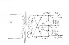
Hope that you are installed two 39K/5W bleeder resistors in parallel with each smoothing capacitor bank , here is the simplified PSU schematic,
bipolar DC voltage have to be around or less than 176VDC unloaded .
Attachments
Hi!
Today I tried my PSU, it is based on the original schematic except that I use parallel 250V caps for the +/- rails. I got very strange results: without load the transformer has 2x125VAC (125.4 and 125.7). The negative DC rails looks O.K. ca. -170 Vdc, but both of the positive rails are much higher! Over 200!
I could not measure right, I had to turn of because it was higher than my caps voltage rating. What can cause this?
I tried with 2v12Vac transformer to check it on lower voltage and I got:
HT1-2: +19.4Vdc
HT4: -17.8Vdc
HT3: -52.9Vdc
Greets:
Tyimo
I think you are encountering a feature that I also ran into. My experience also is that there tends to be a substantial imbalance between the positive HT2 and negative HT4 voltages, especially under low load conditions (as Banat emphasises, you presumably do have the bleeder resistors across the capacitors, right?). The total voltage difference between HT4 and HT2 stays steady (aside from the relatively small decrease when it is loaded), but the balance of HT2 vs HT4 relative to ground can drift.
For that reason, in my OTL amplifiers I always tie the transformer secondary centre-tap to circuit ground, so that the HT2 and HT4 supplies are not "semi-floating." In other words, in Tim Mellow's power supply schematic in fig. 3 in the audioXpress article, I short-circuit the 1Kohm resistor R33.
This has pros and cons. On the "pro" side, it means that the HT2 is firmly held to +150V (or whatever, depending on transformer secondary voltage) and HT4 to -150V, and they can't slide upwards or downwards in unison, unlike what can happen in the "semi-floating" arrangement when the 1Kohm R33 is used. Apart from anything else, I have never liked the idea of the "semi-floating" arrangement when two amplifiers (left channel and right channel) are powered from the same power supply, since a drift in the balance of HT2 vs HT4 relative to ground that results from some condition in one of the two amplifiers then necessarily forces that drift onto the other amplifier too.
On the "con" side, by shorting out R33 it means that if some catastrophic fault condition caused one of the 6C33C tubes to develop, for example, an anode to cathode short, then the full 150V would be applied directly to the speaker cone. One would have to hope that the fuses FS1 or FS2 saved the speaker!
Having said that, all is not rosy if that hypothetical fault condition develops in the case where one does have the 1Kohm R33 as in Tim Mellow's schematic. First of all, the corresponding smoothing capacitor would in any case discharge into the loudspeaker, and I imagine that discharging 2000uF at 150V into a speaker could be quite damaging in any case! If by chance the fuse and speaker did not blow, there would now be a follow-on problem in that the full 300V or so would be applied across the other capacitor, which could exceed its working voltage sufficiently that it might now explode.
In the end, having initially agonised a bit over the question of whether or not to tie the transformer centre-tap to ground I decided to go ahead and do it. I've run this OTL amplifier, and several others, in this configuration for quite a few years now, and never had any catastrophes, so I don't usually worry about it any more.
Anyway, in summary I can only say that I found the vagaries of the "semi-floating" power supply too unappealing, and so I always tie the centre-tap of the transformer to ground.
Chris
Hi Banat and Chris!
Thanks for the answer!
Here is what I did. I wanted to make dual mono amplifier, so I have two 250VA 2x120VAC transformers and two separated PSU boards with the parts.
The strange thing is that I got the -176Vdc, but I got over +220Vdc!
HT3 was also O.K.
Do I need to install the 39K/5W bleeder resistors ? I have not read anywhere about it....
Greets:
Tyimo
Thanks for the answer!
No, I didn't. I followed the original schematic, except that I used parallel 250V caps for the + and - rails.Hope that you are installed two 39K/5W bleeder resistors in parallel with each smoothing capacitor bank
Here is what I did. I wanted to make dual mono amplifier, so I have two 250VA 2x120VAC transformers and two separated PSU boards with the parts.
The strange thing is that I got the -176Vdc, but I got over +220Vdc!
HT3 was also O.K.
Do I need to install the 39K/5W bleeder resistors ? I have not read anywhere about it....
Greets:
Tyimo
Attachments
Last edited:
HT bleeder resistors are always a good idea. If you test the supply stage without tubes installed, they can safely discharge the capacitors before you start working on the hardware. The value should be low enough to discharge the capacitors to a safe voltage over a period of a few seconds when the mains supply is switched off, keeping in mind that your capacitor values may not be the same as someone else's, and OTL amplifiers tend to use larger capacitors than the transformer coupled variety. The wattage rating should be quite a bit higher than the power that will be dissipated by the resistors since they will always be generating heat when the power supply is in use. You ideally need to calculate the values for your design.Hi Banat and Chris!
Do I need to install the 39K/5W bleeder resistors ? I have not read anywhere about it....
HT bleeder resistors are always a good idea. If you test the supply stage without tubes installed, they can safely discharge the capacitors before you start working on the hardware. The value should be low enough to discharge the capacitors to a safe voltage over a period of a few seconds when the mains supply is switched off, keeping in mind that your capacitor values may not be the same as someone else's, and OTL amplifiers tend to use larger capacitors than the transformer coupled variety. The wattage rating should be quite a bit higher than the power that will be dissipated by the resistors since they will always be generating heat when the power supply is in use. You ideally need to calculate the values for your design.
Agreed. And the bleeder resistors might help a bit with balancing up the plus and minus HT voltages too.
By the way, although a catastrophic failure of a 6C33C in which anode shorted to cathode is probably pretty unlikely, there is an almost as catastrophic thing that could actually occur with the Tim Mellow design. Namely, if one of the EF86 driver tubes failed by becoming non-conducting, or if it was simply removed from its socket (or came loose with a bad pin connection), then it could mean that a 6C33C grid would then be connected to its anode via the 100K resistor R12 or R13, with nothing to pull the grid voltage downwards. That would drive the 6C33C heavily into conduction.
I think one can only (a) hope that this never happens due to a sudden EF86 failure; (b) take care never to remove an EF86 while the amplifier is in operation; and (c) hope that the fuses will save the day if the worst ever happens. I always install an additional fuse (of lower amperage rating than FS1 and FS2) in series with the loudspeaker output for each channel, as an additional safety measure.
Chris
Hi Banat and Chris!
Thanks for the answer!
No, I didn't. I followed the original schematic, except that I used parallel 250V caps for the + and - rails.
Here is what I did. I wanted to make dual mono amplifier, so I have two 250VA 2x120VAC transformers and two separated PSU boards with the parts.
The strange thing is that I got the -176Vdc, but I got over +220Vdc!
HT3 was also O.K.
Do I need to install the 39K/5W bleeder resistors ? I have not read anywhere about it....
Greets:
Tyimo
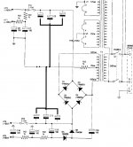
If you look at original T.M. schematic there`s also 8 bleeder 10K resistors installed in parallel with each 8 x 6800uF series connected filter capacitors ,they are from R23 to R30 ,
so definitely you need to install that two 39K/5W bleeder resistors , they can be ordinary ceramic wire wound types .
Edit , those two bleeder power resistors can be even with lower values , let`s say 33K/7W each .
Last edited:
Thanks for everybody!
I will try the 39K/5W, hope it will help to get the ballance.
Another questions:
- How could I test my PSU without to connect to the amplifier? What could I use for the same load?
- For mono amplifier and PSU the R33 1K should stay as it is or do I need different value? I also ask this for the rest of the resistors in the circuit.
Greets:
Tyimo
How can I calculate those two bleeder power resistors value? I would like to learn it.You ideally need to calculate the values for your design.
I will try the 39K/5W, hope it will help to get the ballance.
I thought it was used to compensate the series connected capacitors high resistance....f you look at original T.M. schematic there`s also 8 bleeder 10K resistors installed in parallel with each 8 x 6800uF series connected filter capacitors ,they are from R23 to R30 ,
so definitely you need to install that two 39K/5W bleeder resistors , they can be ordinary ceramic wire wound types .
Another questions:
- How could I test my PSU without to connect to the amplifier? What could I use for the same load?
- For mono amplifier and PSU the R33 1K should stay as it is or do I need different value? I also ask this for the rest of the resistors in the circuit.
Greets:
Tyimo
Last edited:
Tyimo
- Yes originally those R23 to R30 compensate and equalize DC voltage across each series connected capacitors , but in the same time they are bleeder resistors too .
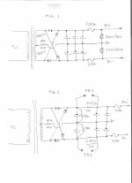
- Rough test of PSU can be done by connecting two same light bulb of 220V/40W across each bipolar line (fig.1)
-Since you use more conventional PSU filter scheme you can connect on each side of bipolar lines one 0R47/4W resistor to get better DC smoothing , by making CRCC filters, but in the same time with inserting of those two 0R47 res. you get two test points for measurements of IQ of output power tubes (fig.2)
-R33 - 1K/10W should remain connected there,
since that resistor limit DC current flow via loudspeaker in case that some 6c33c begin to arcing , or from some reason start to conduct hard , if let`s say 6c33c stays without proper negative DC bias grid voltage .
-and question , what value of capacitors you use for main bipolar PSU?
- Yes originally those R23 to R30 compensate and equalize DC voltage across each series connected capacitors , but in the same time they are bleeder resistors too .
- Rough test of PSU can be done by connecting two same light bulb of 220V/40W across each bipolar line (fig.1)
-Since you use more conventional PSU filter scheme you can connect on each side of bipolar lines one 0R47/4W resistor to get better DC smoothing , by making CRCC filters, but in the same time with inserting of those two 0R47 res. you get two test points for measurements of IQ of output power tubes (fig.2)
-R33 - 1K/10W should remain connected there,
since that resistor limit DC current flow via loudspeaker in case that some 6c33c begin to arcing , or from some reason start to conduct hard , if let`s say 6c33c stays without proper negative DC bias grid voltage .
-and question , what value of capacitors you use for main bipolar PSU?
Attachments
You are welcome Tyimo !
- you can add at least one more 560uF/250V per each side , making CRCCC filters, since by adding more capacitance you will improve bass spectrum response of the amp.
- since this OTL amp use semi floating PSU scheme it is not bad practice to leave PSU in on state for several hours connected as is in fig.1 with light bulb loads ,
in this way electrolytic capacitors become fully formed , and indirectly OTL amp output DC offset become more stable .
-R33 - 1K/10W should remain connected there,
since that resistor limit DC current flow via loudspeaker in case that some 6c33c begin to arcing , or from some reason start to conduct hard , if let`s say 6c33c stays without proper negative DC bias grid voltage .
As I indicated in my previous posting, I think there are arguments pro and con, for whether to retain R33 or short it out. Especially, in the case that both channels of a stereo amplifier are running off the same power supply, it may be that it is safer to short out R33:
Consider the case when R33 is included, so the power supplies are "semi-floating." Now suppose, for the sake of argument, and taking an "extreme" failure, that the upper 6C33C of the right-hand channel develops a short-circuit. This means that the smoothing capacitor(s) for the HT2 supply will suddenly be connected across the RH loudspeaker coil, through fuse FS1. Since that means connecting a 2000uF capacitor charged to 150V across the speaker, it means more than 20 Joules gets dumped into the speaker coil. Three possible things might happen:
1) The fuse blows, saving the speaker. This would also equally have happened if R33 had been shorted out.
2) The fuse survives but the speaker coil blows. This too would equally well have happened if R33 had been shorted out.
3) The fuse survives and the speaker coil survives. This could not happen if R33 had been shorted, since with R33 shorted there would be a steady 150V, through FS1, across the speaker coil, and so certainly one or the other would have failed. This is the only scenario under which it might be thought advantageous to have included R33.
However, if we think about scenario 3 more closely, we have to ask what happens next. With FS1 and the RH speaker coil intact, it means that HT2 is now brought down to ground potential, through FS1 and the RH speaker coil. That means that HT4 will now be at -300V instead of -150V, and so the smoothing capacitor(s) for the HT4 supply will have 300V across them, which very likely exceeds their working voltage by a large margin. There could quickly be a very large current flow through them (and, therefore, through the RH speaker coil), as a precursor to a catastrophic capacitor failure. Thus, the mere fact that the speaker coil escaped the first hazard when the 6C33C shorted doesn't mean it is safe!
Meanwhile, the left-hand channel, which was just an innocent bystander at first, is also dragged into the game. It too finds itself with HT2 going from +150V to zero, and hence HT4 going from -150V to -300V. That is to say, the lower 6C33C in the LH channel is now operating with twice the cathode-to-anode voltage that it is supposed to be getting, while the upper 6C33C has zero volts, and provides no current to balance the greatly increased current passing through the lower 6C33C. This could very well result in the speaker coil in the left-hand channel also at risk of getting fried.
All told, I think I feel more comfortable with R33 shorted out. Now, HT2 is a steady +150V no matter what, and HT4 is a steady -150V no matter what. In failure scenarios 1 and 2 above, one is no worse off than if R33 had been present. And the possibility of scenario 3, which can only arise if R33 is present, and which might end up wrecking both the RH and LH speakers, and output tubes in both channels, is avoided. One should also use separate fuses FS1 and FS2 for the left and the right channels, so that any untoward occurrence in one of the channels does not impact the other channel.
Chris
Quite a nice circuit...
http://www.velleman.eu/downloads/0/illustrated/illustrated_assembly_manual_k4700.pdf
The turn on delay is about 10 seconds, and DC offset protection is applied in about half a second (by my rough calculations). If the DC offset is present at switch on the speaker is never connected. Peak input voltage allowed is also usefully high so that the protection circuit won't blow up under basic fault conditions.
I might get myself one of these just for a bit of insurance for the future.
- Home
- Amplifiers
- Tubes / Valves
- New Tim Mellows OTL project