adamus said:I'll probably go for a buffer with this, but if not, what are the negatives to lowering the 10k output resistors?
Hi adamus,
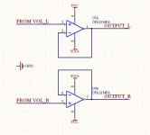
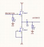
You can add a simple buffer such as a OPA2134 or 2*K170. But if the impedance of your preamp/amplifier is higher than 50K,it's OK to use the VOL kit without buffer.
regards
Lu
Attachments
wirewiggler said:I just ordered one I plan using it with a
pass B1. I hope there is not a issue with impedance matching.
Bill
Hi wirewiggler,
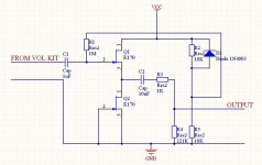
I think there's no problem, please refer to the JFET BUFFER in my last post. Actually , the buffer is the same as B1 ^_^
regards
Lu
I was looking at your drawing and figured it would work. I built a B1 and am using it with my tube amps and am quite pleased with it. I needed another preamp for my F5 and thought your controller with the B1 would be a nice combination. I plan to use the toolreg whenever they finish it up with the B1 as well.
Bill
Bill
wirewiggler said:I was looking at your drawing and figured it would work. I built a B1 and am using it with my tube amps and am quite pleased with it. I needed another preamp for my F5 and thought your controller with the B1 would be a nice combination. I plan to use the toolreg whenever they finish it up with the B1 as well.
Bill
Hi Bill,
This may help ^_^
regards
Lu
Attachments
r-2r
I have just finished putting my R-2R in an old DH101 cabinet with a B-1-such fun
I have the ability to measure harmonic distortion(an old liberty audiosuite) and am having trouble with the R-2R- when it is in the signal path for input switching and volume control. It is introducing some serious 2nd harmonic distortion- re 10x @ 30hz, and 4-5x @90hz, 180hs, 240hz and a general rising trend of harmonic distortion as the frequency ascends. I am using a star ground scheme and spent alot of time last night lifting grounds, moving them to and from the chassis, and putting resistors in the various ground legs to try to lessen the distorion. My leads from the inputs are 24g silver over copper teflon coated alpha core wire with an external braid shield with a return wire from the braid back to the ground point . My lowest distortion came from a 25k ohm resistor between the input ground wire and the star ground. I also used 100k ohm between shield wire to chassis ground - saw some improvement but that 30hz spike( the B-1 was reading.04% distortion @ 30hz by itself but wtih the R-2R in line it rose to about .8%) really has me wondering. It would seem to be power supply related but I saw no difference when I first moved the switching power supply module away from the preamp and then changed the powersupply to a linear supply-makes me think its in the board not the supply- I even cut in some inductors and caps in the power line and saw no appreciable difference-can anyone recomend a cap between the 5v input and ground on the board- has anyone else seen, worked through this kind of issue?
all input(pardon the pun) would be appreciated
rob
All those frequencies are harmonically related to your line - I presume you are on 60Hz - which is very suspicious.
Your kit is presumably PC soundcard based? How familiar are you with it? Used it on other circuits OK?
Do you have a scope to display PSU ripple and waveforms?
It mightalso be breakthrough from the digital display - a 'scope is needed for this.
Your kit is presumably PC soundcard based? How familiar are you with it? Used it on other circuits OK?
Do you have a scope to display PSU ripple and waveforms?
It mightalso be breakthrough from the digital display - a 'scope is needed for this.
r-2r trouble with harmonic dist
Yep the Liberty Audiosuite is PC based-neat piece of kit with fft, o'scope, spec analyser and distortion analyser- about 15 years old but a nice toy-
used it for years designing speakers, just started on electronics-
its ac coupled unfortuneately so I can't look at the dc from the power supply-
my thoughts were the same as yours thinking the problem lay at the feet of the power supply relative to the freqs in question- I started with a small computer type switching pwr/wallwart thang which are reputed to be noisy- but the distortion as measured didn't change when I moved the "wart" some distance from the preamp(though it did look marginally better higher up in freq with some ferrite cores around the power cord) and didn't subside when I swapped in a linear supply- hence my question about some "on board snubbing or cap to ground" intervention-the 30hz distortion is a serious spike
thanks for your input
(once again no pun intended)
rob
Re: r-2r trouble with harmonic dist
Hi rob,
Many thanks for your feedback.
The following step may help:
1. add two copper boards (for ex. two new pcbs) to the top and bottom side of the VOL main board, this may improve the shield condition. For the main board is not small, it may induct 50Hz interference from the human body and environment.
2.when you test the distortion, add a OPA2134 buffer such as I post before, that buffer has a low self distortion.
3. A low distortion signal generator is need ^_^
Thank you for your work again
best regards
Lu
rob lenk said:Yep the Liberty Audiosuite is PC based-neat piece of kit with fft, o'scope, spec analyser and distortion analyser- about 15 years old but a nice toy-
used it for years designing speakers, just started on electronics-
its ac coupled unfortuneately so I can't look at the dc from the power supply-
my thoughts were the same as yours thinking the problem lay at the feet of the power supply relative to the freqs in question- I started with a small computer type switching pwr/wallwart thang which are reputed to be noisy- but the distortion as measured didn't change when I moved the "wart" some distance from the preamp(though it did look marginally better higher up in freq with some ferrite cores around the power cord) and didn't subside when I swapped in a linear supply- hence my question about some "on board snubbing or cap to ground" intervention-the 30hz distortion is a serious spike
thanks for your input
(once again no pun intended)
rob
Hi rob,
Many thanks for your feedback.
The following step may help:
1. add two copper boards (for ex. two new pcbs) to the top and bottom side of the VOL main board, this may improve the shield condition. For the main board is not small, it may induct 50Hz interference from the human body and environment.
2.when you test the distortion, add a OPA2134 buffer such as I post before, that buffer has a low self distortion.
3. A low distortion signal generator is need ^_^
Thank you for your work again
best regards
Lu
I am interested in trying this kit ")
(email sent)
some ideas on the general subject, perhaps for the next version (a dream)
1) allow some general purpose TTL outputs and let us group some of them into a 'radio button' group like the input selector. for example, I'm doing a build that will have a selectable bass boost and I will let the user select 1 of 3 or even 4 settings (but only 1 at a time, exactly like RadioButtons). if there were 4 pins that I could group this way, that would be very useful. somehow it would be nice to select if this group was RadioButton style, ToggleButton style or PushButton style. that would be the ultimate in flexibility.
2) provide board space for an onboard op-amp buffer. some may want to have a buffer and some may not, but if there is board space allowed, then those that want the buffer can easily have it. the rest of us (lol) will just ignore it and everyone will be happy.
3) if your *receiver* were learning, then you would not need to send or include a transmitter in your kit. there is a kit by another DIY vendor that uses a single PAL and lets you program the receive end of things to any remote sender you have at home. you can even mix brands for the various 'slots' (keys). this is useful if you really prefer to continue using your favorite remote handheld and don't want to have to run IT in learn mode. with some extra code on the receiver and a 'learn' button, you can have the user sequence thru all 'n' slots and press the 'n' buttons and you'd save the mappings in local NVRAM. this would bring the usability of a kit like this up a whole new level (very few allow programming at the receive and but it IS the most useful way to be a DIY receiver).
4) if the unit is upgradeable in code (is it?) that would be nice. if we could load new .hex files for fixes or customizations, that's a really nice thing to have.
5) stored volume control settings for each input. as you go from one input to the next, it would 'resume' from the last volume setting used AT that input. you can then 'balance' things across sources to compensate for variations. just another nice-to-have thing; saving the last-used volume setting and recalling that value each time an input-change occurs.
this is just my dream list for such a device. if the source was open, I'd be more than happy to implement this but I'm assuming its going to be closed-source, only? so, I can't help make it happen, but I can only make wishes for them
Re: r-2r trouble with harmonic dist
You should short the input with (say) a 10K resistor and eliminate your generator.
If you are still seeing harmonic spectra it is not the ladder producing distortion (a pretty radical idea for most people) but 60Hz full wave rectifier spikes being injected into the circuit. Spikes do have a high harmonic content.
In this case your PC equipment is of little use - you need to be looking in the time domain not frequency. IE get a simple ANALOG oscilloscope to try and track down where it is coming from.
Ground loop is the most common, but if you can be sure that your powers supply has negligable ripple (only a 'scope will tell!) then it must be picked up from somewhere else.
When you see the effect, try stopping to uP oscillator to eliminate clock pickup.
I don't know how anyone debugs analog stuff without a 'scope - you are left with guesswork!
rob lenk said:Yep the Liberty Audiosuite is PC based-neat piece of kit with fft, o'scope, spec analyser and distortion analyser- about 15 years old but a nice toy-
used it for years designing speakers, just started on electronics-
its ac coupled unfortuneately so I can't look at the dc from the power supply-
my thoughts were the same as yours thinking the problem lay at the feet of the power supply relative to the freqs in question- I started with a small computer type switching pwr/wallwart thang which are reputed to be noisy- but the distortion as measured didn't change when I moved the "wart" some distance from the preamp(though it did look marginally better higher up in freq with some ferrite cores around the power cord) and didn't subside when I swapped in a linear supply- hence my question about some "on board snubbing or cap to ground" intervention-the 30hz distortion is a serious spike
thanks for your input
(once again no pun intended)
rob
You should short the input with (say) a 10K resistor and eliminate your generator.
If you are still seeing harmonic spectra it is not the ladder producing distortion (a pretty radical idea for most people) but 60Hz full wave rectifier spikes being injected into the circuit. Spikes do have a high harmonic content.
In this case your PC equipment is of little use - you need to be looking in the time domain not frequency. IE get a simple ANALOG oscilloscope to try and track down where it is coming from.
Ground loop is the most common, but if you can be sure that your powers supply has negligable ripple (only a 'scope will tell!) then it must be picked up from somewhere else.
When you see the effect, try stopping to uP oscillator to eliminate clock pickup.
I don't know how anyone debugs analog stuff without a 'scope - you are left with guesswork!
jean-paul said:Lu, I sent you an email but maybe you did not receive it. My question is if you include the cables for connecting the input cinch connectors with the PCB ?
Yes jean-paul, I will add four 3Pin cables or four female connectors to the kit.
regards
Lu
R-2R/b-1 update
for those who have been following my project an update;
(for those who haven't I took an old Hafler dh 101 preamp gutted it leaving the power supply and the rca stips and added a R-2R remote volume and input switcher and a Pass B-1 buffer-
wire is 24 guage silver coated ofc copper alfa core with silver coated kimber copper 20 guage buss bars for the rcas, and the B-1 buffer in a quasi star ground arraingment- photos to follow)
Intialy when everything was "in box" I saw quite a bit of power supply related distortion.Relative to a post questioning my conclusions based on my test setup(liberty audiosuite) I tore down the preamp, bypassing the R-2R and still saw high 30hz distortion relative to the rest of the spectra- I raised the levels and the spectra diminished- didn't disappear but went down enough fro me to move on-is that possible with this obssesion?- points to the importance of understanding what and how you are measuring- can anyone say perspective/experience?
Since I was in tear down mode, I decided to upgrade the diodes on the Hafler power supply which was stock at that time. Having done that I looked at the space that was now available inside the enclosure and decided to take the power supply outboard which would leave me room to add a second buffer for my tape/zone 2 output. The fun never ends!
So at this point I have signal coming into an elma 2 pole six position rotary switch, and jumping straight through to the R-2R input switcher- and out of the elma(does anyone remember tape selector switches?) to an old Audio express project called the Morrey super buffer- a ne5534 type buffer. Out of the 2-R2 to the Pass B-1. Power is running 19 volts from another Audio Express Kit called the Valkeyrie which is inexpensive, dual supply(ie + and - outputs) great board and layout, this runs the B-1(main output) and the Morrey Super Buffer(tape output). I am also using a Dell wall wart outputing 5.2volts runs the R-2R. Both power supplys are outboard.
One issue I'm having with the R-2R is that I'm dropping one channel as I raise and lower the volume- sticky relays?- Anyone else having this issue? Lu have you seen this before?
Lastly my two cents for the next iteration would be to include the eyelets in the traces as they go from source selector to volume so one could add a tape out painlessly.
back to the soldering iron
rob
- Status
- This old topic is closed. If you want to reopen this topic, contact a moderator using the "Report Post" button.