sachi said:Good to hear that things have cleared up Lu.
Look forward to corresponding with you for a balanced R-2R attenuator after the festivities.
happy holidays.
Thank you sachi
")
Lu
glad to hear your pp problems have cleared up. Painful indeed.
Picked up my set from the post office on sat and am very happy-thanks!
one comment and two questions
comment
found the unit really does want .5 amp to operate- guess its all those relays- constructors take note.
questions-
1)could you suggest the best place to tap or interrupt the connection between the input switcher and the volume control?
2) I assume you don't need documentation of my shipping for paypal?
thanks for your efforts
rob
Got mine too. When you first power it up, you will hear a loud "zap" and the LCD gets dim. So I thought "I fried it", But after reading the manual, the screen does get dim after applying power because it is in standby mode and the loud "zap" are from the relays "zapping" into mute position.
One suggestion: It would be nice to have the extra two pin function be assigned to the remote and have them behave as an on/off (or toggle) to select other components, for example to actuate a relay that will switch between two digital inputs to a DAC.
One suggestion: It would be nice to have the extra two pin function be assigned to the remote and have them behave as an on/off (or toggle) to select other components, for example to actuate a relay that will switch between two digital inputs to a DAC.
pchw said:Will you honor the promotion price that you OK-ed in the promotion period but got on hold due to the Paypal saga?
Thanks,
YGM
volkit
anyone want to hazard a guess as to where one might tap Lu's source selector/volume board to separate the selector from the volume- I'm thinking of using 2 B-1 buffers for tape out(before the volume control but after the input selector)and one after the volume control to buffer the input into the amp as well as generate a second variable output(sub).
Relative to generating more buffered outputs I was thinking of just adding more 1kohm legs to the output(ie multiple outputs isolated by the resistors). thoughts?comments?
tnx
rob
Re: volkit
Hi Rob lenk,
Could you draw a schematic for what you're describing?
regards
Lu
rob lenk said:anyone want to hazard a guess as to where one might tap Lu's source selector/volume board to separate the selector from the volume- I'm thinking of using 2 B-1 buffers for tape out(before the volume control but after the input selector)and one after the volume control to buffer the input into the amp as well as generate a second variable output(sub).
Relative to generating more buffered outputs I was thinking of just adding more 1kohm legs to the output(ie multiple outputs isolated by the resistors). thoughts?comments?
tnx
rob
Hi Rob lenk,
Could you draw a schematic for what you're describing?
regards
Lu
Re: volkit and tape out
Hi rob lenk,
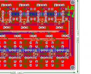
Maybe you can add a relay to the signal path, please look at the picture.The signal paths are on the right side of the main board.
regards
Lu
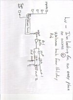
rob lenk said:Lu
I'm looking for a simple place to brake in to the signal after the source switching and before the volume control
see attached schematic
thanks for your interest and I hope you enjoyed your holiday
rob
Hi rob lenk,
Maybe you can add a relay to the signal path, please look at the picture.The signal paths are on the right side of the main board.
regards
Lu
Attachments
Re: volkit and tape out
Hi rob lenk,
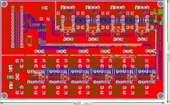
The signal is now always at top of two resistors ^_^
If you want to add a "REC OUT",connect the output you want to the signal path I shown on the picture above, that is ok. You may even not have to cut the copper path on the PCB
Sorry for my silly english
regards
Lu
rob lenk said:Lu
thanks so much for the info and your support-much appreciated.
So the signal is not always at the top of R24 and R42? I have to tap the traces to access the signal before the volume ladder?
thanks again
rob
Hi rob lenk,
The signal is now always at top of two resistors ^_^
If you want to add a "REC OUT",connect the output you want to the signal path I shown on the picture above, that is ok. You may even not have to cut the copper path on the PCB
Sorry for my silly english
regards
Lu
volkit
Lu
I'm quite sure that your use of my language is an effort(and much more accomplished than I would ever be in your language)which I deeply appreciate.
Just to be clear, you recommend tapping the traces for a record out rather than the two resistors I mentioned- Reason I ask is that it would be much simpler to solder onto the resistor leads than to scrape and piggie back onto the traces. I also see where the traces lead into the relay-4 pins down from the top- which also looks like a good place to tap- Do you have any problem with a low temp solder(180 degree f)heating a pin of the relay? Could this damage the relay.
Perhaps in future version os the volkit you could put an eyelet in the trace for a record out? Then we audio weenies could obsess over whether or not to buffer the tape out.
Again, many thanks for your efforts
rob
Re: volkit
You're wellcome ^_^
rob lenk said:Lu
I'm quite sure that your use of my language is an effort(and much more accomplished than I would ever be in your language)which I deeply appreciate.
Just to be clear, you recommend tapping the traces for a record out rather than the two resistors I mentioned- Reason I ask is that it would be much simpler to solder onto the resistor leads than to scrape and piggie back onto the traces. I also see where the traces lead into the relay-4 pins down from the top- which also looks like a good place to tap- Do you have any problem with a low temp solder(180 degree f)heating a pin of the relay? Could this damage the relay.
Perhaps in future version os the volkit you could put an eyelet in the trace for a record out? Then we audio weenies could obsess over whether or not to buffer the tape out.
Again, many thanks for your efforts
rob
You're wellcome ^_^
- Status
- This old topic is closed. If you want to reopen this topic, contact a moderator using the "Report Post" button.