Great jkuetemann.
If you go back to the beginning of this thread,
you see I use simple pair of IRFP240/IRF9240 for output.
The numbers were very good.
This circuit now shown to work good with following outputs
- pure MOSFET pair
- Lazy Cat BIGBT
- Triple darlington BJT
I must say it is a nice Power Buffer.
EVerything points this way.
Next I will go back to the MOSFET output, once again
The somewhat higher input impedance of the MOSFET Gates
is good for the results.
There is also higher voltage across the input transistors.
Like 4+4 Volt.
I spent some time playing with the lower CCS currents to get the circuit into a balanced condition (BTW, the input pair balance is very touchy and important for performance) and got some nice numbers. I'm wondering about some kind of current mirror with one leg reflected to the opposing rail for the front end to keep it well balanced. The diamond pair seems to be more important with respect to output offset and as such I think is best left adjustable. Currents were ~100mA through the BIGBT BJTs and 50mA through the MOSFET driver.
Attachments
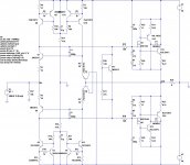
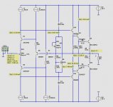
This is a Combined Voltage Amp Opamp
and
The Power Buffer.
The OPamp has got voltage feedback and TMC error correction.
It is rather precise.
The LU Power Buffer is one version with Triple EF.
The buffer and voltage amplifier work separately.
There is no global feedback.
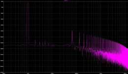
These are the simulated THD figures
We now call this buffer: LU Power Buffer
where LU stands for Lineup")
and
The Power Buffer.
The OPamp has got voltage feedback and TMC error correction.
It is rather precise.
The LU Power Buffer is one version with Triple EF.
The buffer and voltage amplifier work separately.
There is no global feedback.
These are the simulated THD figures
Those a good numbers, but no doubt can be made better with other versions of the LU Power Buffer.Combined VoltageAmpSC2240_1c PowerBuffer_6p
Power Supply is +/-42 Volts
THD 1kHz
04 Vp, 01 Watt THD 0.00016%
08 Vp, 04 Watt THD 0.00024%
12 Vp, 09 Watt THD 0.00034%
16 Vp, 16 Watt THD 0.00044%
20 Vp, 25 Watt THD 0.00054%
24 Vp, 36 Watt THD 0.00067%
28 Vp, 49 Watt THD 0.00080%
32 Vp, 64 Watt THD 0.00095%
36 Vp, 81 Watt THD 0.00115%
40 Vp,100 Watt THD 0.89761%
THD 20kHz
04 Vp, 01 Watt THD 0.00227%
08 Vp, 04 Watt THD 0.00219%
12 Vp, 09 Watt THD 0.00223%
16 Vp, 16 Watt THD 0.00212%
20 Vp, 25 Watt THD 0.00213%
24 Vp, 36 Watt THD 0.00260%
28 Vp, 49 Watt THD 0.00381%
32 Vp, 64 Watt THD 0.00593%
36 Vp, 81 Watt THD 0.00919%
We now call this buffer: LU Power Buffer
where LU stands for Lineup
Attachments
The mirror current source is a good idea.I spent some time playing with the lower CCS currents to get the circuit into a balanced condition (BTW, the input pair balance is very touchy and important for performance) and got some nice numbers. I'm wondering about some kind of current mirror with one leg reflected to the opposing rail for the front end to keep it well balanced. The diamond pair seems to be more important with respect to output offset and as such I think is best left adjustable. Currents were ~100mA through the BIGBT BJTs and 50mA through the MOSFET driver.
The DC Offset should be solved some way.
If people see an Output cap,
they shake their head and go elssewhere.
Myself is not at all afraid of using Output capacitor. Say 10.000uF
When we use NPN + PNP MOSFET output pair
we can get offset like several 0.1 Volt.
Because one MOSFET can have 4.3 and another 4.5 VGS.
One idea is the let the frontend 10+10 Ohm be one trimpotentiometer.
A precision trimpotentiometer of 20 Ohm
and take the input through the wiper somewhere in middle.
This calls for having maybe 0.3+0.3 Volt across the input trimpot.
If this voltage is too low, then the adjustment may not be enough.
Those figures are dissapointing given the low THD from the buffer. Now try a straight forward Blameless amp and use TMC with it. It will result in much better figures.
Yes, I think the bottleneck is the driving circuit. About the buffer itself, it is a buffer, with normally low distortion. Now the question is, is the extra low distortion worth the extra complex buffer circuit. I mean, many other simpler buffers are low distortion, even if they are not super low.
Try to setup a diamond normal power buffer,
and you see what distortion figures you get.
That is what I call disappointing
I agree with homemodder regarding a Blameless with negative feedback and TMC.
But then you have global negative feedback over your ears.
This buffer approach try to get away from GNFB.
And so, like Struth understands we get 2 distinct parts with only local feedback.
Good idea MiiB.What about a Lateral MOSFET output... Could be be good also...
I will try this when I get time.
This might be the best approach. We all know what Laterals can do.
I have the SPICE models of 2SK1058 and 2S162
I will try this when I get time.
This might be the best approach. We all know what Laterals can do.
I have the SPICE models of 2SK1058 and 2S162
Cool, we might put some circuits from the discrete opamp open design thread to drive the buffer. I myself have some opamp projects waiting for this kind of job.
Try to setup a diamond normal power buffer,
and you see what distortion figures you get.
That is what I call disappointing
I agree with homemodder regarding a Blameless with negative feedback and TMC.
But then you have global negative feedback over your ears.
This buffer approach try to get away from GNFB.
And so, like Struth understands we get 2 distinct parts with only local feedback.
Whats wrong with GNFB ??
How can you define as being local feedback. Here you have two GNFB loops, Im not sure which is worse.
Hi Line up checkout http://www.diyaudio.com/forums/solid-state/222133-class-i.html
Hi Guys
Lineup, in my circuit Q5 and Q6 control bias. They symmetrically control both halves of the circuit.
The series combination of the emitter resistors in the output stage has a constant current through it set as approximately 700mV/2Re. So, if you set Re=330mR, then you have 660mR total. The idle current will be 700mV/660mR=1A - actually 60mA higher.
I only need low power, so running class-A does not incur a high heat penalty with the +/-12V supplies.
With the bias cap in place, you can set the class-A output to any arbitrary value you like, despite having much higher supplies than would be needed for that power. The cap allows higher drive to occur and the circuit goes to class-B - I believe Self would say AB here.
The refinements you've made with the triple-EF and capacitive load handling are great! There are countless variations that can be made of this circuit and nearly all will be top performers.
Note that "m" is "milli". 330mR is what some right as 0.33R. Similarly, the 33mF cap is more often written as 33,000uF.
Have fun
Kevin O'Connor
Thanks, Kevin.
So far I have only tested this LU Power Buffer
with standard Class AB with bias set to 100mA in MJL3281A/1302A.
The use of these output devices is because I know I have good models.
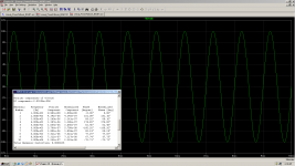
I just tested THE BEST VERSION so far in my SPICE.
I was get stuck with THD 0.00016% at 1 Watt.
It seemed impossible to get lower.
The Cure was to change to other transistors.
I had used only BD139/140 and 2SC2240/SA970.
Now I use 2SC4793/SA1837 and 2N5551/5401.
Voila!!!
The nice numbers are almost frightening.
THD 0.00006% at 1 Watt
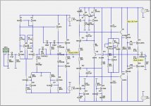
I show here the new and best version with new transistors.
Of all versions I prefer TRIPLE EF output.
So far I have only tested this LU Power Buffer
with standard Class AB with bias set to 100mA in MJL3281A/1302A.
The use of these output devices is because I know I have good models.
I just tested THE BEST VERSION so far in my SPICE.
I was get stuck with THD 0.00016% at 1 Watt.
It seemed impossible to get lower.
The Cure was to change to other transistors.
I had used only BD139/140 and 2SC2240/SA970.
Now I use 2SC4793/SA1837 and 2N5551/5401.
Voila!!!
The nice numbers are almost frightening.
THD 0.00006% at 1 Watt
I show here the new and best version with new transistors.
Of all versions I prefer TRIPLE EF output.
Attachments
Bravo lineupNow I use 2SC4793/SA1837 and 2N5551/5401.
Voila!!!
The nice numbers are almost frightening.
THD 0.00006% at 1 Watt

The same THD number jkuetemann got in post #121
As homemodder said for unity gain buffer that's not so very surprising THD, as complete amp should incorporate voltage gain stage with its own anomalies to correct too. Try to sim something like global CFB symmetrical amp. Hopefully phase margin and OLG bandwidth will show us something special too.
I did a 20kHz test. For 1, 4, 9 Watt so far.
The numbers are promising:
THD 20kHz
04 Vp, 01 Watt THD 0.00022%
08 Vp, 04 Watt THD 0.00072%
12 Vp, 09 Watt THD 0.00119%
Regarding how fast. The last version above is -3dB at well above 10 MHz.
So some little input filter is probably a good advice .......
Lazy Cat,
can you point me to 'global CFB symmetrical amp'.
I might try this.
Hi Guys
The 2N5550/5400 pair have been industry standards since the late 1970s or early 1980s. They are used in many of the best production amps. Some details of their specs are unexciting but their linearity is excellent, producing a balanced distortion spectrum.
Most of the solid-state amps I've built in the past twenty years have been for guitar or bass. In that environment, and because I also use these BJTs in kits related to tube equipment, the high voltage capability of the MPSA42/92 is convenient. They have a pretty flat gain over a wide current range. Again they have some unspectacular characteristics, as well, but are also quite linear devices as Self demonstrated.
Since Toshiba introduced the 2SA1302/2SC3281 and 2SA1306/2SC3298 pairs, I have only used these and similar for hifi amps and drivers in guitar amps. Some of the latter had TO-3 devices since they were the fashion of the day and easy to acquire. Everything has gone to TO-247 and TO-264 for outputs now, which are a convenient package. It is a good thing that Motorola licensed the Japanese technology so they could improve their line of fairly good devices. The MJL21193/94 are pretty much MJ15024/25 die in a TO-3P case. The MJL1302A/3281A are renumbers 2SA/2SC to appease US buyers loath to buy foreign-numbered product.
I assumed you were using BDs instead of better devices out of convenience - you already them or you already had the sim models. It is no surprise that the numbers are better with the more linear devices.
Matching of devices will lower THD and help with DC offset. Device parameters and matching can be made less critical with emitter degeneration in place. The use of Rs instead of CSs pretty much eliminates DC offset based on current imbalance of the CSs and provides a very balanced rise/fall of supplies while maintaining low offset.
Leach suggested a GBW of 8-10MHz is a reasonable range for an amp to have low TIM and otherwise good performance. The LU buffer is in that ball park, so no need to try to make it faster as that is just asking for critical layout problems.
Have fun
Kevin O'Connor
Even though what you said Kevin is the mother ..and basis for a lot of reasonable things there is actually many variables that worth looking at .
A BC 547 for example next to Mpsa XX will also depend on the ""way"" you operate them ...Harman Kardon runs 60 volt drivers ( for example ) at 59.9999 volts and then if current is not enough put two of them in parallel ...which actually plays quite fine and measures even better ...still to my understanding its a very bad practice ...
kind regards
sakis
Sakis I would not say its a bad practice at all, it depends on where the part is used and how. I always use fast parraleled drivers instead of one big slow one like mje15032 series. Harmon know exactly what they doing.
Those BDs are exceptional as drivers although limited by Vce and SOA, two of them can be used in parrallel and they peform better than those toshibas at their max Vce especially at frequencies higher than 1Khz and lower powers.
Lineup is simulating not measuring, reality could be very different. His spice models for the BDs could be incorrect as well as the other models too.
I love to ba able to measure, homemodder.
But I have nothing to do this with.
I have had in the past when I lived in another place.
No doubt reality check with measuring the amplifier can give some unpleasant surprises.
But SPICE is not all bad.
Some people here use both sim and real stuff.
Even if they can measure they can checkup and find problems using SIM.
I am waiting for that guy, that will build ....!!!!
And I am confident in the circuit will work.
How well nobody knows for the moment.
But even guesses can be good.
- Status
- This old topic is closed. If you want to reopen this topic, contact a moderator using the "Report Post" button.
- Home
- Amplifiers
- Solid State
- New Lineup IDEA - Power Follower/Output stage