Hey, OnAudio.Is it possible to have U3, U9, U6 and U7 handle your bias. May have come across a unity gain self biasing output stage ....
Also the current needed to drive this stage is quite high.....you can make a dynamic class A output stage.........
the question remains concerning the sound character of the entire amplifier from input to output....
your on to something if you get it right, still got some ways to go
About setting the bias. No, itnis not possble to let U3U9U6andU7 handle bias for the output.
I do think we can get the current lower.
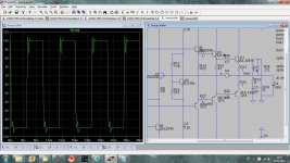
What I have tried so far is 20mA total 10mA throug the frontend. And as can be seen in diagram here below 30mA TOTAL 20 mA through frontend.
The improvement was not big.
The question is WHY should we lower current??
John Curl once said to me: Current is good!!!
I remember this, every now and then ....
---
---
---
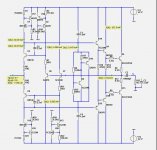
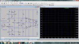
This is the new circuit.
As can be seen it now uses 4 capacitors for compensation and to make the amplifier stable and behave good in capacitive loads.
The input impedance is now very high. More than 200 kOhm.
OnAudio, you ask me about the sound. Answer is nobody know - nobody tried it ..
I have not the possibility to try it in real circuit.
I hope some guy comes along and sees the potential of it.
Regards Lineup
Attachments
I am happy to get a fellow tester.I think I'll have to play with this in sim. I'd like to see it with Lazy Cat's BIGBT's for output devices.
jkurtemann, can you please post the circuit and the result in this thread.
I am looking forward to it
")
Ahahahha!..... current is good to heat the room, melt the snow and to cook eggs
over the heatsinks... i am in facing this with 20 watts of consumption of my Super A... a hell hot.
This amplifier is interesting.... i would like to see someone building and posting pictures and evaluating it real life too.
Simulator results are very good.....now let's see the real thing.... i do imagine it will sound very good.
I am not sure..but it looks this may be another Class A circuit.... because line up loves these heaters.
regards,
Carlos
Last edited:
I am happy to get a fellow tester.
jkurtemann, can you please post the circuit and the result in this thread.
I am looking forward to it
Working on the schematic now, should have something to sim in a while. I'll likely be using different transistor models as I'm using LT Spice. Probably use the Cordell models. We'll see what it looks like.
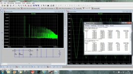
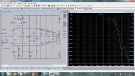
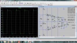
Some simulations, mostly Cordell models used. Bias set to 130 mA.
dado
Hi Dado
please send your simulation comand parameters, graph details looks nice,
thank you in advance
Hi Dado
please send your simulation comand parameters, graph details looks nice,
thank you in advance
You can see all from this screen shot.
dado
Attachments
Great work, dadodYou can see all from this screen shot.
dado
Do you think it is stable in capacitive load,
without those caps across Q3 and Q6.
In my latest version I use 2.2nF there and also 2.2nF across the output transistors.
I think I see you use 1.5nF
To test for stability in capacitive load use 8 Ohm//2.2uF as load.
Attachments
I think that with 2.2 nF as in your last sch you slow the buffer to much, better use output inductance to protect against capacitive load.
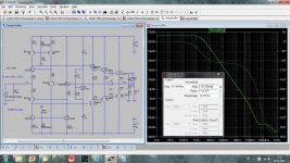
First screen shot with your last suggested compensation there are still some oscilation on 100 nF load. With inductance you can see that there is no oscilation even with 1 uF and 1.5nF comp on predriver only. I did not try different compensation. Zobel was not connected during those simulations, but I would recomment to be used.
dado
Attachments

Lineup Buffer + Lazy Cat BIGBT
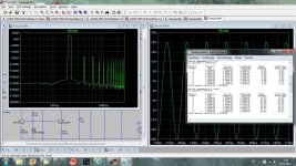
Did not have a whole lot of time to play with this, but does work. Showed almost pure H2 only. Will spend some more time optimizing it to see what I can get out of it. THD was 0.000235% without any optimization and non-ideal MOSFETs used, will looks for spice models for more realistic devices.
Did not have a whole lot of time to play with this, but does work. Showed almost pure H2 only. Will spend some more time optimizing it to see what I can get out of it. THD was 0.000235% without any optimization and non-ideal MOSFETs used, will looks for spice models for more realistic devices.
Attachments
Hi Guys
My situation is similar to Andrew's inasmuch as my speakers are efficient. My listening space is small and I mostly listen at 60db give or take. When we want to crank it, 80db is loud enough and this takes much less than 1W per side. It is nice to have an SPL meter as most people really have no idea how low the db's are when they are listening, but are enamoured with the 120db end of the spectrum.
I built a "slow" version of this buffer replacing the current sources with Rs. I used 2SA1837/2SC4793 for drivers, MJL1302A/3281A for outputs, and MPSA42/92 everywhere else. These have a flatter gain than 2N3904/3906 even though the latter are faster. This was powered from +/-12V. I added base-stops for the diamond feedback input but did not use base-stops on the output transistors.
I used a current-sensing bias circuit that directly monitors Vq across the R-E pair. The two BJTs here are the same as the drivers so they can be bolted to the heatsink. Current will be constant without this mounting, and drops slightly once the heat sink warms up.
I placed a usual size cap across the predriver bases (base to base) and no other compensation. The buffer seems stable into any load I try with it. I would recommend adding a low-value choke in parallel with a low-value R if one needs ultimate stability into capacitive loads. Any zobel at the output should be on the speaker side of the choke.
I consider it a flaw in every opamp and PA circuit I see that does not have a DC path to ground at the output. My buffer has a 1k to ground there and a 56k2 at the input to ground. DC offset is less than 2mV which I consider acceptable. I've never built an amp with more than this much offset and usually my meter cannot resolve it.
The use of resistors here and there helps to dampen tendencies toward oscillation. The input and output Rs provide a needed voltage reference for the input and a tether for the output. The Rs in place of CSs provide a smooth turn-on/off characteristic without thumps, so I do not need a turn-on delay. Resistors instead of CSs can introduce large signal gain variations if you want to utilise the whole supply. For my situation, a 4Vpk signal that is clean is more than I need, so nonlinearity above that point is not an issue for my app. However, I will change the Rs to CSs to test that out. CSs will certainly provide wider bandwidth, as Lineup has already demonstrated, but with Rs instead the bandwidth is still far in excess of the audio band. My oscillator only goes to 1MHz, and the buffer certainly passes clean 100kHz square waves, so its frequency response must extend well past 1MHz even as I've built it. This seems fast enough for audio and some input bandwidth limiting is warranted.
The circuit does not have a sound of its own, which is pretty much ideal! It basically sounds like whatever you drive it with. If you wanted to drive it with tubes, it will sound like tubes; with BJT circuits of various forms, it will generally have that character. Like any BJT buffer, the low output impedance might alter the sound of the driving amp or preamp based on this characteristic.
Back when I suggested adding a diamond buffer to drive the input to have a higher z-in, this was merely meant to be a "variation", not the main design direction.
Have fun
Kevin O'Connor
Hi Guys
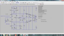
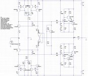
As it happens, I entered the schemo into Eagle last night. I built it with only one pair of outputs but may do my PCBs with two pairs.
The power supply had a pair of 33mF-16V caps per rail, with 100nF rail-to-rail and 6k81 bleeders.
The "LU" in the schemo is for Lineup.
This bias circuit was shown in TUT2 in 1997 (The Ultimate Tone vol.2) in the Solid Stae Power Amps chapter. It will be in the new hifi book coming out January (Designer Notes vol.1).
Have fun
Kevin O'Connor
Attachments
Thanks. I will add inductance instead.I think that with 2.2 nF as in your last sch you slow the buffer to much, better use output inductance to protect against capacitive load.
First screen shot with your last suggested compensation there are still some oscilation on 100 nF load. With inductance you can see that there is no oscilation even with 1 uF and 1.5nF comp on predriver only. I did not try different compensation. Zobel was not connected during those simulations, but I would recomment to be used.
dado
That will keep the distortion low within the circuit,
and at the same time protect against capacitive looads.
Great jkuetemann.Did not have a whole lot of time to play with this, but does work. Showed almost pure H2 only. Will spend some more time optimizing it to see what I can get out of it. THD was 0.000235% without any optimization and non-ideal MOSFETs used, will looks for spice models for more realistic devices.
If you go back to the beginning of this thread,
you see I use simple pair of IRFP240/IRF9240 for output.
The numbers were very good.
This circuit now shown to work good with following outputs
- pure MOSFET pair
- Lazy Cat BIGBT
- Triple darlington BJT
I must say it is a nice Power Buffer.
EVerything points this way.
Next I will go back to the MOSFET output, once again
The somewhat higher input impedance of the MOSFET Gates
is good for the results.
There is also higher voltage across the input transistors.
Like 4+4 Volt.
Welcome to this topic, Lazy Cat.Interesting, jkuetemann you can try to lower R25-R28 to 12 ohms or less to set mosfet driver's current to 50 mA or even higher if that slightly reduces distortions.
Hope you enjoy it and can give good assistance.
Every brain can see and contribute.
This gives the project success and progress
This is what I wanted to test also. Pure resistors to bias the frontend - the diamond.Hi Guys
As it happens, I entered the schemo into Eagle last night. I built it with only one pair of outputs but may do my PCBs with two pairs.
The power supply had a pair of 33mF-16V caps per rail, with 100nF rail-to-rail and 6k81 bleeders.
The "LU" in the schemo is for Lineup.
This bias circuit was shown in TUT2 in 1997 (The Ultimate Tone vol.2) in the Solid Stae Power Amps chapter. It will be in the new hifi book coming out January (Designer Notes vol.1).
Have fun
Kevin O'Connor
Of course this will make much lower input impedance.
And I expect higher distortion.
But it can be a nice simplification to the circuit.
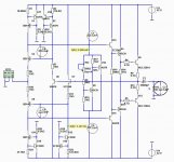
Those Q5, Q6, what are those for?
Are those for controlling bias or for current limiting?
- Status
- This old topic is closed. If you want to reopen this topic, contact a moderator using the "Report Post" button.
- Home
- Amplifiers
- Solid State
- New Lineup IDEA - Power Follower/Output stage