If I understand what I've read here, 8V is not fine. Tillman says 5 to 7V is good, and that seems to be the consensus here too. If I get the theory, the amplified signal can only swing positive by 1V (up to 9V), but it can go negative by a handful of volts. (Or is that the other way around? Anyway.)
I did try it, and it was noisy as hell. So I thought I'd do it thoroughly; first, get statistics for all unknown components (the piezos, the FETs)...
...then, have the circuit designed to fit my components, instead of the other way around.
So, how do I find the impedance?
I did try it, and it was noisy as hell. So I thought I'd do it thoroughly; first, get statistics for all unknown components (the piezos, the FETs)...
...then, have the circuit designed to fit my components, instead of the other way around.
So, how do I find the impedance?
JFET Guitar Preamp
Hi Thomas,
To get your Don Tillman circuit working correctly you may want to refer to posting number 91 and 94 of this thread (if not all my postings concerning JFET biasing). There I tell you how to modify the Tillman circuit for proper operation. I do not believe there is anything wrong with your J201 devices, thier characteristics are most likely just different than the J201 that Mr. Tillman used in his design.
As far as the input impeadance of your J201 amplifier is concerned, I would not use a gate resistor of less than 2.2 MOhm and would experiment with values as high as 10.0 MOhm for piezo transducers. The problem is that the higher value metal film type, through-hole resistors are a little difficult to find at your local store (although, Vishay resistors are available with values of up to 4.99MOhm through Digi-Key); to get around this, you may have to "series" several 1.0MOhm resistors together to determine the optimal value for your piezo pickups.
I hope this helps.
JP Hugsley
Mr. Hugsley,
That I'll do, eventually. However, I was more referring to your post #88:
On another note, is there a special reason you're mentioning metal film resistors? My local electronics store seem to have carbon film ones at 10.0 MOhm, and yes, OK, metal ones (0.6W tolerance) at only slightly higher price.
Metal film=less noise?
Oh, and other points of interest: the instrument in question is a bass guitar, I got the bridges off of eBay, and they didn't come with any numerical specifications.
Thanks,
/Tomas
That I'll do, eventually. However, I was more referring to your post #88:
So I thought, if there's a somewhat simple way to measure the pickups source impedance, I should do so, to get it all as optimal as possible.BTW: I have never designed a preamp for a piezoelectric pickup. It would help to know the source impeadance of such a pickup. Do you have this information? If not, could you give me the name and model of your guitar, maybe I could reseach this information myself.
On another note, is there a special reason you're mentioning metal film resistors? My local electronics store seem to have carbon film ones at 10.0 MOhm, and yes, OK, metal ones (0.6W tolerance) at only slightly higher price.
Metal film=less noise?
Oh, and other points of interest: the instrument in question is a bass guitar, I got the bridges off of eBay, and they didn't come with any numerical specifications.
Thanks,
/Tomas
Since we are talking about impedance, there is no single measure for it. You would have to do a sweep at various frequencies. A piezo is pretty much like a crystal circuit and has a dominant capacitive characteristic along with some resonating components. All you effectively need to know is that the source impedance is very high (most piezo pickup manufacturers suggest interfacing to at least 10 Megaohm input) and that loading the pickup will degrade the bass response, which is opposite to what happens with magnetic pickups.
Rather than using a high-value input resistor that is both hard to get and will add noise why not use “gate feedback” (split the source resistor in two and connect the gate resistor to their junction point) or some even furtherly advanced method of input bootstrapping where the input is referenced to the FET’s source? Both techniques will easily let you overcome the limit of the input resistor’s value. Done right, the latter method can even result to effective input impedances in the order of several hundreds of megaohms while still using only ordinary component values that are less than 3 Mega-ohms. (Granted that this requires techniques such as CCS loading the source). Anyway, even that omitted you can easily get an input impedance in the order of 30 – 50 Megaohms with conventional components. Unfortunately, Google doesn’t seem to give any hits to related theory but if my memory serves me correct, I think there were some examples in Ray Marston’s series of articles titled “FET Principles and Circuits”. They should be found online somewhere.
Rather than using a high-value input resistor that is both hard to get and will add noise why not use “gate feedback” (split the source resistor in two and connect the gate resistor to their junction point) or some even furtherly advanced method of input bootstrapping where the input is referenced to the FET’s source? Both techniques will easily let you overcome the limit of the input resistor’s value. Done right, the latter method can even result to effective input impedances in the order of several hundreds of megaohms while still using only ordinary component values that are less than 3 Mega-ohms. (Granted that this requires techniques such as CCS loading the source). Anyway, even that omitted you can easily get an input impedance in the order of 30 – 50 Megaohms with conventional components. Unfortunately, Google doesn’t seem to give any hits to related theory but if my memory serves me correct, I think there were some examples in Ray Marston’s series of articles titled “FET Principles and Circuits”. They should be found online somewhere.
So, if I got this right; source impedance, when measured correctly, yields a graph that shows the ohmage at various frequencies, and this graph may or may not have a good mathematical approximation? And to measure it, I'd need a tone generator?
And as long as the input impedance of the preamp is greater than it, it'll all work out fine, so I really only need to focus on getting that as high as possible?
Excuse my noobness.
I have those articles already; haven't been able to fully wrap my head around them yet, though.
And as long as the input impedance of the preamp is greater than it, it'll all work out fine, so I really only need to focus on getting that as high as possible?
Excuse my noobness.
I have those articles already; haven't been able to fully wrap my head around them yet, though.
JFET Guitar Preamp
Hi Thomas,
I have never built a preamp for a piezo pickup so I'm not an expert on the subject but, after posting #81, I did a little research on the impedance charateristics of a piezo pickup. The gentleman in the "teemuk" posting is correct, the piezo element is capacitive in nature and therefore exibits a very high impeadance at low frequencies which "roll-off" as the frequency increases (just like capacitive reactance). As the previous posting states, the lower your gate resistance, the greater the attenuation of your low frequencies will be (not good for a bass guitar).
With a lowest frequency of interest being fixed at about 5 Hz (f) or so and a more-or-less constant capacitive value for your pickup (C); you're going to need a gate resistance that can be approximately calculated by the capacitive reactance formula: R = 1/(2*pi*f*C).
Unfortunately, I could not find any capacitive specifications on bass piezo pickups. For that reason, you may have to experiment with values between 2.2 MOhm and 10 MOhm on your "Tillman" circuit. If you start off with 2.2MOhm and your sound is "tinny" (lack of low frequency content) then you should step-up the value of the gate resistance.
The previous posting was also correct in stating that you could get very high impedances with a "boot-strapping" or "positve-feedback" configuration on a source-follower or common-source circuit but be aware that, with the addition of a constant current source on some of the configurations, you may lose a big chunk of headroom with a 9.0Volt power supply (of course, you could always make it an 18 Volt system). In any case, it's always worth a try.
As far as metal-film resistor being less "noisy" than a carbon film resistor, this is true. Is the noise level really that noticeable? Many would think so. Also, the metal film resistor has other charateristics in TC and stability that make it more desirable. On the negative side, they are harder to get in the higher Ohmage values and are slightly more expensive.
I hope this helps,
JP Hugsley
Tomas,
Such a buffer has to have 5-10MOhm input impedance. I showed you already one example - the schematic from Carvin. In the left bottom corner you have such a buffer - with 4MOhm input impedance. It takes just 10-20 minutes to build it and verify whether it works. As you can see there the buffer has gain < 1 because with piezo it is not needed. You can use also Tillman preamp just with reduced gain and increased gate resistor.
Mark
Better FET for powered preamp
I want to thank the members here, especially Hugsley, for all that I've learned reading your posts.
As I understand it, the reason the J201 was chosen for the Hugsley and Tillman designs was that it worked well for low-current operation. Is there a JFET that you would suggest when low power consumption is not an issue, but high fidelity (low noise) is?
Alternatively, which are the most important characteristics that should be similar to the J201 as I look for a part? Which characteristics should be different for this application (beyond the obvious equivalent input noise voltage)? Thanks!
-Vance
Low noise jFET type
Hi, as far as 'low noise' goes, I once sampled LSK389 and LSK170 from http://www.linearsystems.com.
They sound good (as usual, all is relative and depending on the circuit it is operating in) and are low noise enough for me.
If more gain is needed, try someting like a Mu-amp/Minibooster.
Regards,
Bart
JFET Guitar Preamp
Hi Vance,
There are many JFETs available that are recommended by the manufacturer for audio applications; some of the more popular devices are: 2SK170, 2N5457, 2N5458, 2N5459, 2N4117, 2N4119, KSK30 (Fairchild), LS846 (Linear Systems), 2SK369, and 2SK373 (Bart seems to like the 2SK389 and 2SK170)
You will find that these devices are usually optimized for use as either high-gain preamplifiers or line-level amplifier signal chains. You shouild have no problem in finding the right JFET for just about any intended, low-level audio application you have in mind.
Many other JFETs are recommended for RF and Switching applications and, although they may be suitable for audio, they ususally emphasize, as well as supply data for, specifications that are of less concern to a purely linear audio application (e.g. input capacitance (impedance parameters), switching speed, RDS-on and maximum ID current).
I have gone into detail on JFET specifications for an "on-board" application where the power supply voltage (9 Volt battery) and current draw were paramount; however, in the case of an off-line application (e.g. a power amplifier front-end), relativley high-voltages and larger bias currents will often help with low-noise performance and lineratity.
Have Fun,
JP Hugsley
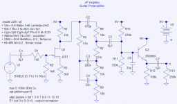
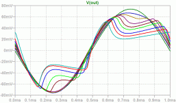
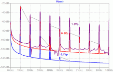
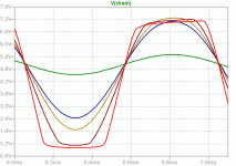
Here's the simulation output showing the effects of varying levels of overdrive. The undistorted waveform is with a 100mV peak 1kHz input. All the other waveforms have been normalized to this level and range from 05Vp to 1.5Vp at the input.
If you examine the family of curves carefully, you can clearly see increasing second harmonic distortion with increasing overdrive (note how clipping begins much sooner on the positive half of the waveform). -- a.s.
If you examine the family of curves carefully, you can clearly see increasing second harmonic distortion with increasing overdrive (note how clipping begins much sooner on the positive half of the waveform). -- a.s.
Attachments
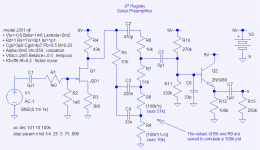
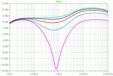
This next schematic is set up to simulate the small signal ac response of the preamp. It is the same as before except that R8 and R9 in the tone control section have been stepped in value to show the effect of combining and replacing them with a 100k potentiometer. -- a.s.
Attachments
This plot shows the frequency response of the simulated preamp as its 100k tone control pot is stepped through 0, 25, 50, 75 and 100 percent. -- a.s.
Disclaimer: This is not meant to necessarily match the tone control response of JP Hugsley's actual preamp, which may have its tone control configured differently to that shown in the simulation presented here.
Disclaimer: This is not meant to necessarily match the tone control response of JP Hugsley's actual preamp, which may have its tone control configured differently to that shown in the simulation presented here.
Attachments
JFET Guitar Preamp
Hi Analog Spiceman,
Excellent simulations. Next we'll have to get the response curves and FFT at various levels and tone settings of the preamp on my bench. It will be interesting to see how close we get between simulations and actual hardware. I have acces to an AP but it may be a week or so before I get the time to run the tests.
Can you please tell me what the IDSS and VGS-off is of the JFET you used in your simulation. I'll try and match them with a JFET I have in my shop.
Thanks again and excellent work,
JP Hugsley
Re: JFET Guitar Preamp
The data sheet for the actual part lists an Idss of 0.2mA to 1.0mA and a Vgs_off of -0.3V to -1.5V.
The simulation values are Idss=0.60mA Vgs_off=-0.6V as set by the following SPICE model:
.model J201 njf
+ Vto=-0.6 Beta=1m6 Lambda=2m2
+ Rd=1 Rs=1 Is=0p1 Isr=1p1
+ Cgs=3p0 Cgd=4p7 Pb=0.5 M=0.23
+ Alpha=0m5 Vk=250 ; ionization
+ Vtotc=-2m5 Betatce=-0.5 ; tempcos
+ Kf=0f6 Af=0.2 ; flicker noise
Here is a plot of the simulated drain voltage waveform under various levels of input drive. -- a.s.
JP Hugsley said:Can you please tell me what the IDSS and VGS-off is of the JFET you used in your simulation. I'll try and match them with a JFET I have in my shop.
The data sheet for the actual part lists an Idss of 0.2mA to 1.0mA and a Vgs_off of -0.3V to -1.5V.
The simulation values are Idss=0.60mA Vgs_off=-0.6V as set by the following SPICE model:
.model J201 njf
+ Vto=-0.6 Beta=1m6 Lambda=2m2
+ Rd=1 Rs=1 Is=0p1 Isr=1p1
+ Cgs=3p0 Cgd=4p7 Pb=0.5 M=0.23
+ Alpha=0m5 Vk=250 ; ionization
+ Vtotc=-2m5 Betatce=-0.5 ; tempcos
+ Kf=0f6 Af=0.2 ; flicker noise
Here is a plot of the simulated drain voltage waveform under various levels of input drive. -- a.s.
Attachments
Hi Analogspiceman,
Great simulations - I did the same (although I've just started learning LTSpice - with great help from you and Helmut ). I have few questions/remarks to your results:
- isn't the unsymertic clipping a result of specific Vgs(off) assumed in the J201 model?
- I'm not sure whether in reality you can get 1.5V from guitar pickups. What is a typical signal level from guitar pickups? I think it's rather closer to 100mV than to 1V.
- What will be the result of the second harmonic appearing on the output - the famous "valve sound"?
- The filter used in the preamp is a typical "Enhance" filter used in many guitar/bass amplifiers. In some cases there is "Enhance" pot and in some cases the filter is fixed - without a posibility to change the frequency response of the filter. If there is a pot, it's usually connected differently than you used in your simulation. Why did you connect the pot in the way you did? (I will try later to post how it is usually done in amps).
- I think that after checking the simulations I will build the preamp and see how it actually works.
Mark
Great simulations - I did the same (although I've just started learning LTSpice - with great help from you and Helmut
- isn't the unsymertic clipping a result of specific Vgs(off) assumed in the J201 model?
- I'm not sure whether in reality you can get 1.5V from guitar pickups. What is a typical signal level from guitar pickups? I think it's rather closer to 100mV than to 1V.
- What will be the result of the second harmonic appearing on the output - the famous "valve sound"?
- The filter used in the preamp is a typical "Enhance" filter used in many guitar/bass amplifiers. In some cases there is "Enhance" pot and in some cases the filter is fixed - without a posibility to change the frequency response of the filter. If there is a pot, it's usually connected differently than you used in your simulation. Why did you connect the pot in the way you did? (I will try later to post how it is usually done in amps).
- I think that after checking the simulations I will build the preamp and see how it actually works.
Mark
Markus2006 said:- isn't the unsymmetrical clipping a result of specific Vgs(off) assumed in the J201 model?
Pretty much, although you could look at it turned around and say that it was due to the selection of the values for the source and drain resistors.
Markus2006 said:- I'm not sure whether in reality you can get 1.5V from guitar pickups. What is a typical signal level from guitar pickups? I think it's rather closer to 100mV than to 1V.
JP Hugsley (we are friends offline) is more of an expert on the music/ instrument related side of things, but my understanding is that a loud guitar riff can produce up to 200mV rms with peaks of several volts. By the way, the leakage inductance of the pick up can be well over a Henry and will form a damped second order low pass with the preamp's input capacitance/ resistance and, depending on the loading, may completely level the apparent high end boost in the response curve I posted earlier.
Markus2006 said:- What will be the result of the second harmonic appearing on the output - the famous "valve sound"?
I think this is part of it, but others might be more qualified to comment on that.
Markus2006 said:- The filter used in the preamp is a typical "Enhance" filter used in many guitar/bass amplifiers. In some cases there is "Enhance" pot and in some cases the filter is fixed - without a possibility to change the frequency response of the filter. If there is a pot, it's usually connected differently than you used in your simulation. Why did you connect the pot in the way you did? (I will try later to post how it is usually done in amps).
I tried placing the pot in several locations and just liked the shape of the response contours that one produced. What other locations would you suggest?
Markus2006 said:- I think that after checking the simulations I will build the preamp and see how it actually works.
Please do.
Regards -- analogspiceman
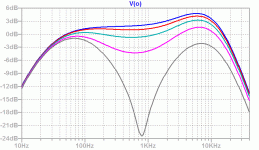
PS: Here's the output response with the typical guitar pick up model in place on the input.
Attachments
Hi all,
While I don't have the electronics expertise you guys have, I have been working with guitar electronics for many years and l know a bit about guitar preformance. I've built LOTS of op-amp style preamps but this is the first discreet component type I've tried and I've learned much from the experience - thank you J.P. Hugsley!
First, Mr. Hugsley shows in his detailed description / tutorial of working with FETs that the source and drain resistors are dependent upon the Vgs cutoff voltage and Idss; they should go hand in hand.
Secondly, large 'humbucker' style pickups can produce 2 volts of sustained output if pushed and I'm sure higher spikes, but normal output is far lower. That said, one must plan for the higher outputs - some guitarists assail their instrument with unbridled passion.
And lastly, the preamp I built per Mr. Hugsley's plans has a ton of high end boost and practically nothing can overcome or dampen it. I replaced C6 with a 47 pf cap and still its highs are very strong. In fact, I installed a pot for the treble control (per his suggestion) and included a bypass switch (a pull knob) so that I could get a completely muted sound. The stock tone control does almost nothing while the preamp is used, and even with the preamp's tone control all the way down and the stock control down as well some shine still gets through. So cord capacitance or effect devices would never present a problem for it.
Hope this was relevant and or helpful info.
Ken
- Status
- This old topic is closed. If you want to reopen this topic, contact a moderator using the "Report Post" button.
- Home
- Live Sound
- Instruments and Amps
- New JFET guitar preamp project
