Warmth, high-end boost and test results
The "warmth" effect most are looking for in a FET (or even tube) preamp is what you see happening between the dark green and dark blue traces in Analogspiceman's waveform plot. Visually, it appears that the peaks are being flattened or widened or rounded (though this only appears to happen on the positive peak in the plot).
This effect both adds even-order harmonics (the 2nd harmonic most predominantly), and something a little bit like compression in that signals of different input amplitudes have more similar output amplitudes.
I suspect that even the dark green plot would show some of the flattening/widening compared to the pure sine wave input. This flattening is because you are pushing into the less linear regions of the device, whereas the area around the zero crossing (or rather 1/2 VDD crossing) is pretty linear.
WRT treble, I've got up and running the first stage of a circuit similar to JP's. It runs at 12V and the corresponding values setting the current parameters of the J201 are different, but it is very similar otherwise. It does not have the tone enhancer circuit or the post-tone buffer amp from JP's circuit.
It does a good job of preserving the treble that is already in the signal, but does not seem to add to the treble. The output has a very balanced sound, and even running at low input amplitudes, is a <b>lot</b> warmer than going into my op-amp-based Mackie mixer.
I have a dual preamp built, and have been playing a Chapman Stick (stereo out) through it a lot with very good results as long as I keep the Stick volume controls turned down (it has more gain than I need at the moment). The Stick goes all the way from below the low E on a bass guitar to the upper reaches of a regular guitar, and the preamp sounds good for the entire range. Lots of thanks to the guys here for the knowledge to make this happen!
Next I plan to experiment with adding a tone stack (I'm going to start with a Fender-ish one) and I intend to build another dual preamp for an acoustic guitar. The guitar has a piezo pickup and a small electret mic that needs phantom power (pretty easy). I'm thinking about using an op-amp (the 5532 is very quiet) for the output buffer stage on both dual preamps. I intend to add a mixed output (the two channels mixed together) as well. Any thoughts about all this would be welcome.
-Vance
sepulchre said:And lastly, the preamp I built per Mr. Hugsley's plans has a ton of high end boost and practically nothing can overcome or dampen it. I replaced C6 with a 47 pf cap and still its highs are very strong. In fact, I installed a pot for the treble control (per his suggestion) and included a bypass switch (a pull knob) so that I could get a completely muted sound. The stock tone control does almost nothing while the preamp is used, and even with the preamp's tone control all the way down and the stock control down as well some shine still gets through. So cord capacitance or effect devices would never present a problem for it.
If you put 100k and 47pF in parallel with the input (R2/ 1M in the simulation schematic) it will definitely take the high end shine off the response curve. If not, you have one very unusual pickup coil.
Regards -- analogspiceman
Hi Analogspiceman,
A couple of questions: did you mean a 100k pot with the 47 pf? Also, would a 100k in parallel with R2 reduce the input impedance significantly? I got the impression that a lower input impedance would put an unwanted load on the pickup.
My pickups are standard Strat single coils; nothing special.
Thanks for your response,
Ken
JFET Guitar Preamp
Hi Guys,
If you want to cut down the high frequencies a bit you can make the mod that Analogspiceman suggests. This mod would not load down your pickup in the main response band (of course, a 100K Ohm resistor without a 47pF cap in series placed in parallel across the input resistor of the preamp would load down the pickup making it sound "muddy").
Another approach would be to change the 33pF capacitor, C6, to a larger value (I would suggest 100pF). This would have the added benifit of cutting down the noise generated by the JFET (kind of a "de-emphasis").
Mark, The SWR SM400 tone ciscuit is a very clever variation of the standard tone-stack. I'll have to try that one out.
Thanks,
JP Hugsley
Hi JP!
Thanks! I tried changing C6 to a 47p value but it didn't do much. I'll try the 100p. If that's not enough I'll try the front end method that Analogspiceman suggested, though that would require an added control; I don't want the shine to be gone all the time.
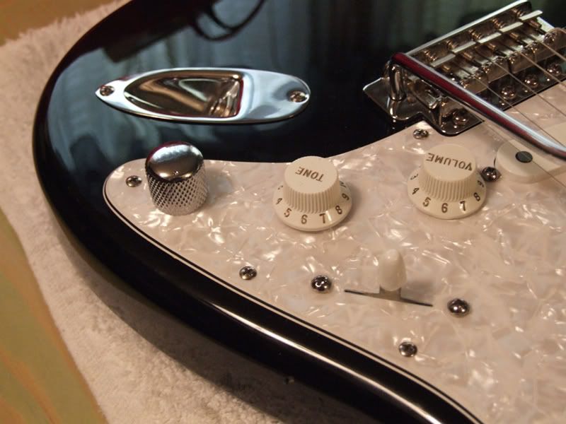
I added a treble control in the tone section per your suggestion and made it a pull switch to bypass the preamp when needed. I used a Tele knob so it wouldn't be hard to get a grip on. Looks kind of different but it works well.
Ken
Thanks! I tried changing C6 to a 47p value but it didn't do much. I'll try the 100p. If that's not enough I'll try the front end method that Analogspiceman suggested, though that would require an added control; I don't want the shine to be gone all the time.
I added a treble control in the tone section per your suggestion and made it a pull switch to bypass the preamp when needed. I used a Tele knob so it wouldn't be hard to get a grip on. Looks kind of different but it works well.
Ken
I think that it is not clearly stated how the resistor and the capacitor should be connected. It seems to me that Analogspiceman wanted them to be connected in series and not in parallel (Analogspiceman please correct me if I'm wrong) - and then finally parallel to R2.analogspiceman said:If you put 100k and 47pF in parallel with the input (R2/ 1M in the simulation schematic) it will definitely take the high end shine off the response curve.
Regards -- Analogspiceman
JP Hugsley, if you look carefully at the SWR Aural Enhancer, you will find that this is exactly the same filter as in your preamp (with added two resistors and a pot). Only the component values are slightly changed - this is a bass guitar preamp and the frequency response has to be different.
I've seen similar filters in many guitar and bass amps - it is not specific to SWR.
Mark
Sepulchre,
Obviously the easiest way to reduce highs in this preamp is to change R6 and R7 resistors (from 10k and 51k) to 33k and 33k. The results will look like this -> see atachment. And it looks almost like the "Character" filter (different name for "Aural Enhancer") in EBS TD350 bass amp.
Mark
Obviously the easiest way to reduce highs in this preamp is to change R6 and R7 resistors (from 10k and 51k) to 33k and 33k. The results will look like this -> see atachment. And it looks almost like the "Character" filter (different name for "Aural Enhancer") in EBS TD350 bass amp.
Mark
Attachments
Well, I replaced R 6 & 7 with a pot so I could have an active adjustment. It works fine. It's the Very high freqs I want to cut down, and I think raising C6 to 100pf should do the trick. I'll let you know when I get it done . . . if I ever get time; work, work, work. Ah well, the bucks gotta come from somewhere.
Thanks for the tip though. The graph shows much about the filter charateristics.
Ken
Thanks for the tip though. The graph shows much about the filter charateristics.
Ken
The original version of the preamp has high frequencies boosted much more than low frequencies (by several decibels). This may be good for a bass guitar with old strings but not good for Ferder Stratocaster which has already a lot of high frequencies. But by tweaking filter parts it can be corrected. Next week I'll have boards for this preamp and I'll finally check it with a guitar.
Mark
Mark
JP Hugsley,
Can you recommend good SMT capacitors for your preamp? I consider WIMA polyester (or polyethylene) capacitors: http://www.wima.com/EN/smdpet.htm . Did you use standard ceramic caps?
Mark
Can you recommend good SMT capacitors for your preamp? I consider WIMA polyester (or polyethylene) capacitors: http://www.wima.com/EN/smdpet.htm . Did you use standard ceramic caps?
Mark
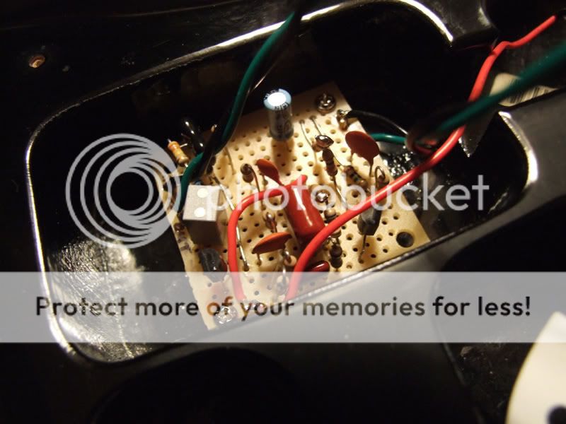
Here's mine. I used a variety of capacitors; whatever was available. Sometimes I wish I lived nearer a big city so I could find parts, but I traded my urban lifestyle for cleaner air, etc.
Anyway, as you can see, this Strat came with a preamp from the factory which never worked. I don't know how it got past their inspection but I got an extraordinary deal on it and it's got lots of room for mods.
I'll be interested to know what you discover with yours.
Ken
Anyway, as you can see, this Strat came with a preamp from the factory which never worked. I don't know how it got past their inspection but I got an extraordinary deal on it and it's got lots of room for mods.
I'll be interested to know what you discover with yours.
Ken
Capacitors
This guy has a hierarchy of what he thinks are the best sounding capacitors for audio. He is a fan of the expensive teflon capacitors, which I have never used, and recommends that you stay away from elecrolytic, tantalum and ceramic discs. Of course, this only applies to the signal path, not bypass or power supply capacitors.
http://www.audiocaps.com/
I have been using polypropylene film capacitors with good results, like these:
http://search.digikey.com/scripts/DkSearch/dksus.dll?Detail?name=P3488-ND
The ceramic discs don't sound terrible, but I found that they tend to degrade over time, so I stopped using them. (I have an old Moog synth that needs to have all of its ceramic discs replaced to be fully operational.) I use the electrolytics and tantalums for power supply and bypass capacitors, respectively, but not for the signal path.
-Vance
Hi Vancestik,
Can you get polypropylene film caps in small values like 33pf? Also, I build circuits that require tantalum caps like the Tube Screamer TS808 circuit, so there's no getting around them at times. It's difficult to get them out here in the field. Order houses want minimum orders of $25 and have way overpriced shipping. Unfortunately Small Bear doesn't handle them. You wouldn't know of a place that does smaller orders would you?
Also, do silver mica capacitors have any inherent sound qualities, good or bad?
Ken
68pF is the lowest capacitor value most part houses carry of any type. With minor adjustments, you can usually use these instead. If you are doing a tone stack, try halving the resistor values in the filter while you double the cap values.
You can get metalized film polypropylene caps at least this low. For instance:
http://search.digikey.com/scripts/DkSearch/dksus.dll?Detail?name=2222 464 76809-ND
As for the tantalum in the TubeScreamer, they are using the peculiar distortion that tantalums give (compared to the cleaner sound of the polypropylene) as part of the unique sound. I used to have an original TubeScreamer, which I loved the sound of. But it disappeared somewhere along the way before they became sought after.
Anyway, good luck!
-Vance
Thanks Vancestik! I'll check out the site.
Btw, if you're handy with a soldering iron:
http://www.generalguitargadgets.com...5&phpMyAdmin=4a28f86a515b7883e7bc35a68d4e7b6d
Otherwise a rereleased TS808 is about $170. The TS9 is around $95 and can be converted to an 808 by replacing two resistors. . . incase you were interested.
Ken
Btw, if you're handy with a soldering iron:
http://www.generalguitargadgets.com...5&phpMyAdmin=4a28f86a515b7883e7bc35a68d4e7b6d
Otherwise a rereleased TS808 is about $170. The TS9 is around $95 and can be converted to an 808 by replacing two resistors. . . incase you were interested.
Ken
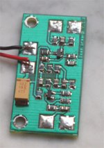
My version of the preamp looks like this (see attachment). The board design is not perfect - this is my first SMT project. The next version would be significantly different (if I had time to do it).
I have problems with low precision of ceramic caps. But the preamp works well - I did only some initial tests - it wasn't tested on stage.
Mark
I have problems with low precision of ceramic caps. But the preamp works well - I did only some initial tests - it wasn't tested on stage.
Mark
Attachments
") .
.Great thread folks.
My backup bass is has a P-J pickup combo. I currently have the two passive pots hooked up as balance and volume. My main bass has the same setup but with EMG active pickups and an EMG preamp. Besides routing out the body for the J pickup, I also had to route out room for the preamp and the two batteries.
I don't want to go quite that radical with this bass. So I was going to hack up a little buffer/mixer. Then I happened on this thread. Perfect!
Since I already have all the components for a through hole implementation, I think I will just grab the board that Markus (I think it was he) posted.
I haven't decided what to do about the tone stack though...do I skip it, or hard wire it (maybe trim pots), or route out enough space for a stacked tone pot? I go back and forth on this...
My initial thoughts on going active was to just stick a common source JFET as both mixer/buffer and driver. But I kind of like the idea of adding an EF for a driver. Certainly gives one more flexibility on setting up the first stage bias since the output impedance is buffered by the EF. sorry, rambling...
- Status
- This old topic is closed. If you want to reopen this topic, contact a moderator using the "Report Post" button.
- Home
- Live Sound
- Instruments and Amps
- New JFET guitar preamp project