Upupa Epops said:I mean, that very interesting should will be, if you compare this results, but by different output levels. I mean, that if is distortion small, ear or brain stop this perceive like distortion, but if this level of distortion is not constant, we perceive it like " tail " below music.
This was one of the reasons why to use the FM method. You can see that e.g. test signals FM no.4 and FM no.6 contain original components at different amplitudes. The signal no.4 that is used in my plot contains components with amplitude difference of some 90 dB in steps of 5-18 dB. The amplifier under test processes every of those components at different power level. And you can see the result, especially for the less linear amplifier.
PMA,
have you tried this type of test signal on amlifiers?
amplitude modulated sine burst
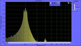
(I tried once but with a not so good sound card on a laptop - results in the image. The device tested is a volume control.)
MBK
have you tried this type of test signal on amlifiers?
amplitude modulated sine burst
(I tried once but with a not so good sound card on a laptop - results in the image. The device tested is a volume control.)
MBK
Attachments
Well, one should test across the entire spectrum of course, say, in 1/3 octave spacings.
I just tried the 100 and 200 Hz AM sine burst that is on Linkwitz's test CD that is designed to test speakers. Nothing precludes producing higher freq. signals for testing amps...
MBK
I just tried the 100 and 200 Hz AM sine burst that is on Linkwitz's test CD that is designed to test speakers. Nothing precludes producing higher freq. signals for testing amps...
MBK
MBK said:Well, one should test across the entire spectrum of course, say, in 1/3 octave spacings.
I agree. The reason why I test on higher frequencies is that I have found nothing interesting when testing at low frequencies.
Toneburst
For amp testing, you might want most severe of tonebursts - single wavelet.
Its a carrier AM modulated by raised cosine of carrier. If single wavelet is passed through amp, its practically impulse with limited BW. Wavelet has spectrum of carrier +/- carrier, ie. 0, Carrier and 2*Carrier. Just two components.
It can also be constructed by summing 2 sine generators, then its wavelet train without gaps. 3 concepts converge here: wavelet, AM modulation, and simple harmonic synthesis.
Wavelet with carrier 20kHz is quite a severe signal for amp as it stresses its slew rate capabilities, linearity and ringing stability.
If single wavelet is sent, it is also safe to feed 100% power through the speakers, afaik.
If you construct repeating wavelet train, then you can quite easily make spectrum analysis.
But in terms of spectral content, its just 1st and 2nd harmonics. its most spectrally clean impulse you can think of.
Attachments
sound card artefacts
Pavel,
I have tried to use my soundcard for measurements and have begun from the card itself (I think, I'm not exception here") ). I have got the same periodic 7.5KHz,
). I have got the same periodic 7.5KHz,
15KHz, 22.5KHz, .... peaks as I can see at your FFT diagrams. The only
difference is "my" peaks are not doubled.
What is these peaks reason?
Andrew
Pavel,
I have tried to use my soundcard for measurements and have begun from the card itself (I think, I'm not exception here
). I have got the same periodic 7.5KHz,15KHz, 22.5KHz, .... peaks as I can see at your FFT diagrams. The only
difference is "my" peaks are not doubled.
What is these peaks reason?
Andrew
PMA said:The reason is the PC environment and its repetitive interference.
Try small frequency modulation, like 1Hz deviation, 1Hz modulation.
Pavel,
Soryy, I have prepared a (not very long) questions list for you
1. I have FM source inside a spice simulator only yet
Nevertheless I'd liketo understand the meaning of your suggestion. Will you add few words
about it?
2. Have you tried to do something to reduce PC-enviromet peaks beyond
mesurement methodology (shields, different slots, ...)?
3. And - probbly OT for this thread - last question is: I don't remember a thread
you have concluded that AD844 is the only (among you have tested) opamp
which is superior in comparison with some of discrete schematics. Is it
possible to see this schematics?
Andrew
Andrew,
ad 1) the slight FM to the test signal unsettles periodicity of the PC own interference products,
ad 2) I have started to use differential amplifier before the soundcard input, see my page (new distortion measurement ...), this has helped loop problems, does not eliminate PC internal interference. My soundcard is external.
ad 3) the schematics can be seen on my web: PM-AB1, i.e. error correction amplifier.
Pavel,PMA said:ad 3) the schematics can be seen on my web: PM-AB1, i.e. error correction amplifier.
I mean the schematics of gain stage with discrete parts wich is better than all tested
opamps except for AD844. Probably, "VAS" abbreviation is appropriate here
(is "VAS" something like "voltage amplifier stage"?)
Andrew
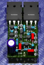
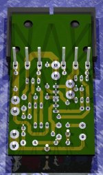
I am just publishing a friend's good art work
Related the circuit quality, i cannot talk too much, as i assemble this one 20 years ago, or maybe more..i do not remember the result.
But Pavel Macura, the name, by itself is a good presentation.
Greg Erskine made the "art work"
regards,
Carlos
Related the circuit quality, i cannot talk too much, as i assemble this one 20 years ago, or maybe more..i do not remember the result.
But Pavel Macura, the name, by itself is a good presentation.
Greg Erskine made the "art work"
regards,
Carlos
Attachments
- Status
- This old topic is closed. If you want to reopen this topic, contact a moderator using the "Report Post" button.
- Home
- Amplifiers
- Solid State
- New distortion measurement method for audio amplifiers