Yes, my recommended Raw DC build uses schottky barrier diodes, with no associated recovery time problems.The reverse recovery time and magnitude play into this, some diodes have no reverse recovery, which may be worth looking into.
It's best to put all the big caps in together, but if you prefer to mount the last cap in the signal chassis, it's probably OK.Is it important that all parts of the raw DC supply is located in the remote chassis?
Uptick mentioned the recharge (current) pulses - and these are the reason to keep the caps away from the signal part. To be closer to the problem: the cables carrying the DC feed (+ recharge pulses) can couple into the B+ Raw DC cables, if the B+ supply is in the power chassis. Many constructors like to bundle all the cables into one connector, and here you may find some noise pickup problems.
So if you put the final caps in the signal chassis, run the cables away from anode-supply cables, and it should be OK. Similarly, inside the signal chassis, keep the DC cable away from signal cables and other parts.
The chokes you are using in the Raw DC will probably lower the recharge pulses anyway.
Ah, recharge pulses, that answers my question. I thought for a second that it had something to do with the distance between the last cap and the regulator.
With LCLC filters, the recharge pulses into the last cap should be fairly small compared to what we would see in an CRC circuit, I believe.
Thanks for your replies!
With LCLC filters, the recharge pulses into the last cap should be fairly small compared to what we would see in an CRC circuit, I believe.
Thanks for your replies!
Rod, using a high AC impedance to feed the DHT filaments would reduce the effect of the filament power supply, but would (I suppose) if left unbypassed to ground, also provide negative feedback.
Does your circuit use a center tapped resistor as return for the plate supply? With fixed bias there can't be much AC left on the unbypassed end of the filament?
Does your circuit use a center tapped resistor as return for the plate supply? With fixed bias there can't be much AC left on the unbypassed end of the filament?
Twisted pairs sounds like a good idea, especially as I'm more or less stuck on bundling all the wires together.
My gut feeling tells me that cap recharge pulses may not be a huge problem in this project since all the DC rails are either LCLC or CLC-filtered. I hope I'm not wrong here...
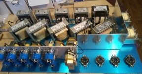
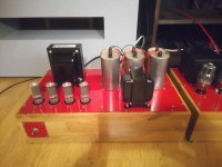
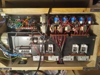
A few hours of "Iron Tetris" has paid off well, it seems I'll actually be able to squeeze all the LV supplies into one chassis with the cores of the transformers, input chokes and filter chokes pointing in three different axis:

My regulators will function with the centre-tap installed, but they sound better with only the negative connected.Rod, using a high AC impedance to feed the DHT filaments would reduce the effect of the filament power supply, but would (I suppose) if left unbypassed to ground, also provide negative feedback.
Does your circuit use a center tapped resistor as return for the plate supply? With fixed bias there can't be much AC left on the unbypassed end of the filament?
Discussions with an active 300B manufacturer (EML) concluded that wear equalisation would not result in a worthwhile increase in lifetime.
But if an AC waveform is required for trials of wear-levelling, I would think that simply wiring the filament terminals tube-sockets of the amplifier stereo pair to opposite polarity. Swap over the DHTs anually, (having rechecking the anode current) to achieve the levelling.
Dynamic waveform generation is relatively complex, and needs to eliminate in-band + subsonic 1/f noise to a very high degree.
I took a look at your DHT heater circuit concept and came up with a variation in LTspice, that would have a lower "burden" voltage, like one volt, while having 90dB gain at DC, uV noise, temp stability, using N- and P-MOS-FET's for lower heat dissipation, with both drains facing the load. Yes, higher capacitance (~ 1nF on the positive side) than BJT's, but not an issue with the plate-supply grounded side.
Not sure how much "music" signal is on the non-grounded side of the filament, typically 3 - 4 Ohms above ground?
A 300B in P-P has a maybe 50mA max current variation during play, so a 200mV music signal, in a 300 - 350V circuit (-65dB), that would be attenuated by 1nF in pparallel with ~4 Ohms?
Have you noticed a difference bypassing both ends of the filament?
A small 1mH inductor could be added in series, but would need another 0.4V for my 3.25A loads, to increase isolation from AC supply.
@Rod Coleman:
It seems I can't access the docs on your web page anymore. Could you please tell me the minimum input voltage required for your V9 regs when used with 6B4G tubes?
My PP amp is finally playing but some of the transformers or chokes in the PSU are buzzing, even though I tested them carefully on the bench before building to avoid exactly this problem. I think my raw DC is a bit on the high side so with some luck I can cure this just by lowering the AC input to the filament transformers, possibly by using the primary winding of my vastly overrated Hammond 370LX HT transformer as an autoformer and "steal" some juice from an unused 100V tap.
BR
Daniel
Not that I'm aware of, but it's not unlikely. Perhaps someone can do me a favor by accessing the "Add regulator to your amps" document and take a look in the section with raw DC voltages for different DHTs and let me know what it says about 6B4G? I have read that document several times and I already have the regulators in my amp so I'm definitely not trying to steal som classified information here or something, just can't remember the miminum input voltage for 6B4G now that I need it 
Thanks, Ian!
Maybe I had better put up some PDF versions on the server.
Google is probably seeing you have some Google cookies and expecting you to be logged in. If this is the case, it should work ok if you use a new private window in Firefox (incognito in Chrome). It shows up for me if I test it in a separate browser with no Google account running.
It works in Incognito mode, thanks everyone!
I'll report back when I've had time to experiment a bit with the filament supplies. The PSU chassis is very, very heavy and putting it back on the bench is a bit of an undertaking. If it turns out I have to tear it apart for any major modifications, I'll consider splitting HV and filament supplies into two separate chassis.

I'll report back when I've had time to experiment a bit with the filament supplies. The PSU chassis is very, very heavy and putting it back on the bench is a bit of an undertaking. If it turns out I have to tear it apart for any major modifications, I'll consider splitting HV and filament supplies into two separate chassis.


Lowering the input voltage to from 230 to 208VAC didn't help much against the mechanical buzzing. This decreased the DC from 11,1V to 9,95V, so I should be able to lower the AC input down to maybe 195V before the regs fall out ouf regulation. Doubt it would help though. Dammit, I tested the transformers and chokes before building the power supply just to avoid this. Perhaps the easiest fix would be to buck the input voltage down to 150V or so and remove the input chokes, not a very tempting solution though.
If you are using an LC (choke input) filter, please check that the choke current rating is well above the DC load current.
Chokes can make a mechanical buzz if there is any risk of saturation.
LC filters at 1A can be improved by adding a solid polymer (Kemet A750 series) 220 .. 470uF 16V right after the rectifier. Not many capacitors can handle the current in this position, please don't use ordinary Alu elkos here.
Chokes can make a mechanical buzz if there is any risk of saturation.
LC filters at 1A can be improved by adding a solid polymer (Kemet A750 series) 220 .. 470uF 16V right after the rectifier. Not many capacitors can handle the current in this position, please don't use ordinary Alu elkos here.
- Home
- Amplifiers
- Tubes / Valves
- New DHT heater