Should be alright for linear or low-power digital timers. Cheap industrial timers can have variable levels of conducted and radiated emissions, and it would be a shame to spoil the quiet environment!What about using a little of the filament's raw supply current for a timer/relay circuit?
Yes, do try to avoid generic PN bridges - they can be noisy.Since I would prefer slightly larger margins, could I replace the generic silicon diode bridge with Schottky diodes? The choke input filter worries me a bit here, since I've read some reports about choke input filters killing solid state rectifiers.
LC supplies for Ampere-level filament supplies are possible; I think the best solution is to make the configuration into cLC.
The first cap needs to be around 330µF for a 1,5A supply, maybe 560µF for 3A. The rms current in the capacitor is too high for ordinary electrolytics - a polymer type is required. [Look at the rms column of I(C1) in your PSUD2 results table].
The Kemet A750 series has parts that can support 3 - 5A and that is plenty for this purpose.
This capacitor limits the unwanted transient voltages out of the bridge recitifier, especially at startup.
The choke should not be operated too near the maximum current rating; LC supplies are more stressful than CLC for the choke. you might get buzzing if it gets too close. IF in doubt, ask the choke maker, and give the AC peak voltage across it, and desired current.
cLC filtering sounds interesting. I have some old 30uF/160V russian paper in oil caps that seem quite indestructable, perhaps a few of those in front of the input choke would work. Will take a look at the Kemet A750 caps too and see if I can find them somewhere.
Regarding the chokes I have at least three different models that seem to handle the duty as input choke, one Hammond (28mH 2A I think) and two different no-name surplus models, three 25mH 3A double C core and a pair of 112mH 2A EI-core. The Hammond choke is the only one still available if I need more.
The big 112mH ones would probably make the best input chokes thanks to their high inductance, but the smaller C-cores also seem to do the job without making any mechanical noises.
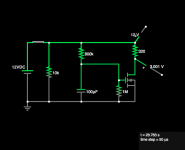
I'm thinking of something like this to short an inrush limit resistor on the B+. (The 'Must operate" voltage of the 320Ω relay is 9V , hence the 12V-3V difference at the stop time around 29 seconds. Total circuit draw is just over 30mA)Should be alright . . .
Attachments
I have some Qs about filament transformers. First a little background:
A page or two back in this thread I mentioned that I'm collecting parts for a 6S4S (6B4G) SET. After auditioning some amps that I already have I changed my mind to PP instead and ordered new output and interstage transformers from Lundahl (LL1682 and LL1660S).
I'm obviously gonna need two more filament regulators too.
The surprisingly problematic part to find is good transformers for the raw DC supplies. Ideally, that would be four separate split bobbin EI transformers.
Turns out such transformers are neither easy to find nor cheap, at least not in my country.
As far as I can understand from reading this thread, fixed bias PP with the cathodes connected to ground through low R current sensing resistors should be one of the more forgiving topologies when using non-optimal filament transformers?
Using this Lundahl power transformer with 8 x6,6V 3V windings (series connected in pairs and and used with LC input filters) would be both cheaper and more convenient than buying, for example, four Hammond EI transformers: https://www.lundahltransformers.com/wp-content/uploads/datasheets/2738.pdf
Though, Lundahl's C-core transformers are more or less the opposite of the split bobbin EI-core design that we want here.
TME sells in you county -too- Indel split bobbin transformers.Turns out such transformers are neither easy to find nor cheap, at least not in my country.
For "small" tubes 40VA is enough.
https://www.tme.eu/se/katalog/trans...&search=ts40&mapped_params=2:337;101:1445764;
Yes, that's right. The PP sides should cancel any 50Hz noise well enough.As far as I can understand from reading this thread, fixed bias PP with the cathodes connected to ground through low R current sensing resistors should be one of the more forgiving topologies when using non-optimal filament transformers?
The reason for suggesting split-bobbin transformers is simply that they have low PRI→SEC leakage capacitance.
for example: A good 50VA split-bobbin might only have 50 .. 75pF of leakage; and at 230V line voltage, the 50Hz leakge current is usually <10µA. This current flows in part of the filament, and in any cathode resistor or bypass capacitor, back to safety earth (PE). The current is common-mode, and there are no (practical) filters that can help, and the type of regulator used make no difference to CM current.
The LL278 solution, used with choke-input should work; it may be worth asking about the PRI→SEC leakage capacitance (please report it here, if you do!).
Indel transformers are good. I list Hammond part numbers in the manual, because the availability is stable, and most countries have a reseller. Many industrial cities have transformer-making factories, and can supply split-bobbin PTs; it's always worth looking a web-search, asking about custom builds.
Thanks for your replies, Rod and Euro21.
TME does ship to Sweden and I have taken a good look at Indels EI transformers. They have a few models that would suit my needs but I must say their core clamp assembly look a bit, well, cheap and they don't seem to be impregnated with varnish? The buzzing from vibrating power transformers is one of the worst aspects of this hobby IMO.
I guess the best option would be to work a little overtime and then order a complete set of Hammond EIs and chokes from Tube Town or Don Audio. Until then I'm aiming at getting a prototype up an running with an old Tektronix PT that has all the HT and filament windings I need for the whole amp.
Believe it or not, but all six of my regulators worked at first try and four of them are even in a good enough condition to be used in my 6C4C PP amp. The remaining two can still be used for SE experiments. Assembling thru-plated PCBs turned out to be a bit of a challenge for someone who almost exclusively builds point to point stuff
Attachments
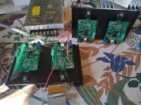
Thanks! I used a soldering station with a very small tip so I can't blame the gear, it was just my clumsiness and lack of skills that made the whole project a much bigger mess than it should have been. A lesson learned, and after all all of them are operational although the two spare boards are not very pretty.
Now I'm waiting for the transformers and chokes, they should arrive from the Netherlands any day now.
Now I'm waiting for the transformers and chokes, they should arrive from the Netherlands any day now.
I'm late t this thread, but I think Rod's idea is good, high impedance isolation of DHT filament for audio is good.
While you can get away with old school AC transformer circuits, for audio amplifiers they did not have the same expectations back then. However if you tried this with RF the results would not be subtle, filament chokes are needed to keep the RF drive power from disappearing into the filament supply.
The analog would be to use large high current chokes on both lead to isolate all audio from the power supply, big and expensive., and the ground the grid and feed the input signal into the filament, one cap on each filament lead.
A VT4C/211 with 1200V plate, -80V grid, (~ like 30mA quiescent) and the 10V DC filament voltage, would have an uneven current distribution. 10V makes a 25% difference in idle current. (I don't think any SPICE model accounts for this effect.) AC current would spread out the current distribution over the filament.
The long term aging effect bias on oxide coated filament could be augmented by reversing polarity every so often. Thoriated tungsten filaments do not have that aging effect.
The effect of a filament heater regulator could be tested like an grounded grid RF amp, feeding the signal into the filament connector. The +B return would be in the input of the Filament Regulation Circuit, aka choke in the RF setup.
The filament supply interaction may be more obvious this way.

Quoted from Mr Colemans page:
"Separate Power Chassis? Transformers rectifiers & capacitors can take up space, and cause electromagnetic coupling into signal wiring/parts. Mounting them in a separate chassis and connecting to the Amp chassis with 1 metre of cable (‘umbilical’) can work very well - the Coleman regulator is designed to work perfectly like this. Mount the Regulator near the tube socket, and put all parts of the raw dc circuit in a remote chassis, or separate case under the amplifier."
Is it important that all parts of the raw DC supply is located in the remote chassis? I'm running out of space really fast here and things would be much easier if I could put the last cap(s) inside the amplifier chassis.
Remoting a 50Hz magnetics is a good idea. Feeding DC into the cable will reduce hum challenges.
Filtering low frequencies is also harder than HF, and if decades out of the audio range intermods will be less of an issue. 250KHz is pretty mundane for DC/DC converters. Have not checked availability.
Checking your circuit with a oscilloscope is a must. Inaudible signals can still be a problem.
Filtering low frequencies is also harder than HF, and if decades out of the audio range intermods will be less of an issue. 250KHz is pretty mundane for DC/DC converters. Have not checked availability.
Checking your circuit with a oscilloscope is a must. Inaudible signals can still be a problem.
I'm with you so far, uptik. I'll only allow well-filtered DC into the amp chassis in this project, no AC at all except of course for the signal.
Each raw DC supply will be built as follows: 14-0-14V transformer - dual Schottky diode - 28mH 3A choke - 4700uF - 6mH choke- 2x4700uF. The question is if it somehow would be detrimental to put the last of the three 4700uF caps inside the amp to save some space in the already crowded PSU chassis? The manual seems to advice against it, but I can't seem to understand why.
Each raw DC supply will be built as follows: 14-0-14V transformer - dual Schottky diode - 28mH 3A choke - 4700uF - 6mH choke- 2x4700uF. The question is if it somehow would be detrimental to put the last of the three 4700uF caps inside the amp to save some space in the already crowded PSU chassis? The manual seems to advice against it, but I can't seem to understand why.
The bulk of the current peaks from the rectifier may be absorbed by the first two caps, the inductor or the lead inductance will slow down the current rise-times thus the alternating magnetic fields around those wires from the PSU box. The sharp cutoff of the diodes will excite some leakage inductance in the mains transformer, a trick some used is to measure the frequency of the resonance and construct a filter for that frequency, which I never did, but well bypass diodes with resistors and caps, as to not allow a sharp turn off. The reverse recovery time and magnitude play into this, some diodes have no reverse recovery, which may be worth looking into.
Are you feed a directly heated triode with this?
Are you feed a directly heated triode with this?
- Home
- Amplifiers
- Tubes / Valves
- New DHT heater