My phone is giving up the ghost, this is hopefully the last picture I take with it before buying a new one tomorrow.
I grew tired of banging my head against the wall with the Hammond chokes and decided to have a look at some alternatives. Luckily I'm a bit of a hoarder so I had six double C core chokes taken from scrapped wire electric discharge machines. Smaller than the Hammonds but with almost twice the inductance and twice the Dcr. Quite surprisingly, four of them handled 18VAC in my test rig without making any audible noise, the last two buzzed very quietly.

I grew tired of banging my head against the wall with the Hammond chokes and decided to have a look at some alternatives. Luckily I'm a bit of a hoarder so I had six double C core chokes taken from scrapped wire electric discharge machines. Smaller than the Hammonds but with almost twice the inductance and twice the Dcr. Quite surprisingly, four of them handled 18VAC in my test rig without making any audible noise, the last two buzzed very quietly.
A basic look at feeding DHT heater with an AC transformer, with a center tap to ground, would present both terminals of the DHT with equal inductance and AC voltage. (This is normally done with DHT for grounded grid RF amplifiers, where the grid provides isolation between in and out and reduces chances for unwanted feedback.)
The issue with AC on audio filament is the audible frequency of the heater voltage, and hum-bucking may not be perfect.
The Signal Voltage of the filament end should be proportional to the frequency dependent reactive impedance of the heater windings, plus others, and any Signal Voltage which would be in phase with the plate current would provide some negative feedback. Mixing mains heater frequency with audio signals would incur a high probability of intermodulation products, F1+F2, F1-F2 etc. Not an issue with DC. Adding said "bonus" inductance to the DC feed would allow similar (frequency dependent) negative feedback. How much inductance?
I grabbed a 60Hz transformer from my junk pile with a 5V 2A winding measures 580uH / 0.25 Ohm at 100Hz, 0.69 Ohm at 1KHz, 24.3 Ohm at 10KHz. If it had a center-tap, those values would be half.
This would suggest more negative feedback at the higher frequencies.
Is this where the magic happens?
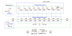
Rather than struggling with an AC supply, or a Fancy DC supply, why not add those inductance values, or similar, to the output of a DC supply? Using a resistor splitter would additionally even the Plate current distribution over the filament, and provide a flat frequency negative feedback to whatever value is desired, using two resistors.
Then the DC filament supply output should not be connected to ground.
Inductors are added to the the DC output, both + and -. Something like the M1439-ND could work.
This would additionally also reduce some noise from the output of the DC supply. .
Even a power line filter of the AC-inlet type could work for the DC filament supply.
I'm sure this has been tried before...
The issue with AC on audio filament is the audible frequency of the heater voltage, and hum-bucking may not be perfect.
The Signal Voltage of the filament end should be proportional to the frequency dependent reactive impedance of the heater windings, plus others, and any Signal Voltage which would be in phase with the plate current would provide some negative feedback. Mixing mains heater frequency with audio signals would incur a high probability of intermodulation products, F1+F2, F1-F2 etc. Not an issue with DC. Adding said "bonus" inductance to the DC feed would allow similar (frequency dependent) negative feedback. How much inductance?
I grabbed a 60Hz transformer from my junk pile with a 5V 2A winding measures 580uH / 0.25 Ohm at 100Hz, 0.69 Ohm at 1KHz, 24.3 Ohm at 10KHz. If it had a center-tap, those values would be half.
This would suggest more negative feedback at the higher frequencies.
Is this where the magic happens?
Rather than struggling with an AC supply, or a Fancy DC supply, why not add those inductance values, or similar, to the output of a DC supply? Using a resistor splitter would additionally even the Plate current distribution over the filament, and provide a flat frequency negative feedback to whatever value is desired, using two resistors.
Then the DC filament supply output should not be connected to ground.
Inductors are added to the the DC output, both + and -. Something like the M1439-ND could work.
This would additionally also reduce some noise from the output of the DC supply. .
Even a power line filter of the AC-inlet type could work for the DC filament supply.
I'm sure this has been tried before...
Attachments
Yes, I 've seen some hardcore DIY:ers using big inductors to isolate the filaments from the DC supplies. I used LCLCL filters in my old 6B4G SET, something like 20mH-22000uF-20mH-44000uF-112mH if I remember correctly. Might try something like that again when I build the prototype for my upcoming 300B SET, it would be interesting to compare it against Rods regulators.
Lundahl makes chokes with dual windings that can be arranged to filter both differential and common mode signals, they should be ideal for something like this.
Lundahl makes chokes with dual windings that can be arranged to filter both differential and common mode signals, they should be ideal for something like this.
The inductors in my simulation are small, ~ 0.3mH. The effect of inductance in a DHT AC filament power transformer is minimal, but maybe important. Using resistors across the heater gives more, or less, of feedback, compared to above. Two inductors, two resistors. Simple.
Not to say a constant current-like supply would not offer more feedback, if that would be a desirable, from its higher impedance. May be worth investigating.
Not to say a constant current-like supply would not offer more feedback, if that would be a desirable, from its higher impedance. May be worth investigating.
Here's what Michael Koster wrote on the subject in an old post at Audio Asylum:
"There are at least 2 different purposes for multiple filament chokes that may impact the selection. First is reducing ripple voltage to the filament. The L between the 2 capacitors in a pi-section filter, or the choke of a choke input critical L filter, does this. Less hum in the output is the result. You can use PSUD to size this choke along with the filter caps. This choke is before the last filter cap and I don't really think of it as a "filament choke", rather as a "filament supply smoothing choke".
The purpose of a second filament choke is to de-couple the audio signal on the filament from the DC supply to the filament. There will be an audio current in the filament due to the finite resistance of the filament. It has been noticed that "better" sound is produced if this audio current is not "shorted out" or loaded down by the DC filament supply filter cap. So the second choke is there to allow the audio voltage to appear across the filament resistance. The current-induced signal voltage in the filament is related to the cathode signal current and the filament resistance. The filament needs some signal reference to ground because it's the cathode, which explains the resistor connection used with the common mode choke. For this choke to work properly, it needs to have AC reactive impedance significatly greater than the filament resistence at the lowest audio frequency of interest, for example 20 or 30 Hz.
Your 813 has a 2 ohm filament resistance (10V/5A) and ~2000 ohm plate resistance in triode mode. Any signal current at the anode will appear as a signal current through the filament returned through it's cathode connection. The filament choke allows a corresponding signal voltage to develop across the filament. For this to work over the audio range, the filament choke needs to have an AC reactance of say 10 ohms at 30 Hz (about 50 mH).
I guess RF can be supressed also, but I don't believe that's the main purpose."
You do not need large iron chokes to filter out ripple, a solid state regulator does that. The noise should be in the microvolt range. Chokes on a DC supply would only mimic the inductive effect of a filament transformer, if that is a bonus, but resistors across the filaments to the plate supply return would have a more even effect than an inductor.
Any inductor has a stated value plus other effects, which turns into a can of worms.
Any inductor has a stated value plus other effects, which turns into a can of worms.
Chokes or regulators to filter out ripple is a matter of preference I guess, and at least at higher currents the chokes are probably quite good at keeping nasty rectifier spikes away from the signal circuitry. Producing clean DC shouldn't be much of a problem in 2023, what's more interesting is the hypothetical inductor between the last cap/voltage source and the filament.
Kosters statement that the reactive impedance at the lowest frequency of interest should be significantly greater than the resistance of the filament makes sense to me.
My 112mH 2A EI-core chokes should present an inductive reactance above 20 ohms at 30Hz, which is significantly larger that the 4-5 ohms of a 300B filament.
Interesting for someone like me who likes plenty of copper and iron in my amps just for the hell of it, but I can predict that Mr Coleman will soon will remind us that a CCS does the same job as an almost infinitely large choke, only smaller but at a fraction of the cost, size and weight
Spikes from rectifiers can excite leakage inductance's in a transformer, the SiC diodes (S3D06065F) supposedly have no reverse recovery, and may be quieter. Whatever resonances, they can be measured and a filter constructed for the specific frequency. Also putting rectifiers directly to (negative) ground is questionable. Some resistance in series with a rectifier could help, if the voltage loss is tolerable.
Good to know, I just ran a test on my PSU after replacing the chokes and guess what...? It's buzzing. Something is wrong here, I tested each of these chokes less than 24 hours up to 18VAC and they were all fine, no buzzing or noises. The tests were made with a transformer with a single secondary winding and a bridge rectifier while the real filament transformers have 14-0-14V secondaries FWCT-rectified by dual schottky diodes.
I guess it's either a problem with the proximity between the filament transformers and the chokes or that my FWCT rectifiers somehow behaves different than the bridge recifier and causes ringings.
Perhaps the next logical step is to disconnect three out of four filament supplies and experiment with different rectifier arrangements on the fourth one to see if that makes any difference. Luckily it should be easy now after rearranging the wiring quite a bit and the transformers have dual secondaries that can be wired in series or parallel. Wish me luck, stopped being funny a while ago...
Nope, wasn't that... Disconnected three out of four supplies and temporarily replaced the Schottkys with generic silicon diodes: No change. Connected transformer 1 to choke 4 to see if creating some distance between the core would help. It didn't, but I learned that both the transformer and the choke contributes a bit to the noise. Easier to locate sounds when the sources are 20+ centimeters apart. At last I used only one secondary winding to feed a bridge rectifier instead of the FWCT arrangement. You guessed it: No change.
I'm running out of realistic ideas here again. Filling the whole chassis with epoxy or resorting to black magic are not realistic ideas, at least not yet...
I'm running out of realistic ideas here again. Filling the whole chassis with epoxy or resorting to black magic are not realistic ideas, at least not yet...
I wonder if you could have some mains DC offset. If you're sure you're not overloading the transformers maybe try looking at this.
A couple of members posted that they have stopped transformer buzzing with the simpler circuit posted below. Never done it myself.
A couple of members posted that they have stopped transformer buzzing with the simpler circuit posted below. Never done it myself.
Attachments
Yes, I've thought about that too. Would be worth a try. Adding resistors in series with the secondaries seems to help at least to some degree, I will experiment further with that. I've thought about putting the rubber dampers back under the transformers too but they didn't help much the first time and they were a bit too soft, allowing the transformers to move around too much inside the chassis and thus potentially causing safety issues.
I guess I have to draw a line somewhere too about how picky I can allow myself to be in this matter. The new chokes are at least less noisy than the Hammonds and if it can be improved further with resistors in series with the secondaries then perhaps I can live with it. A DC trap on the input could perhaps helt a bit more with the noise from the transformers.
The only realistic way I can think of to get things completely silent with the existing chokes and transformers would probably be to decrease the voltage drastically with a bucking transformer and add big electrolytics directly after the rectifiers. Quite an ugly hack though...
Last test for tonight: I wired up a bucking autoformer to lower the input voltage to 160VAC. Even at this voltage both the filament transformers and the input chokes are still buzzing very slightly. Bypassing the input chokes with clip leads to get CLC filters instead of LCLC produces 11Vdc into 10 ohm dummy loads.
Don't ask me how the chokes could handle 18VAC without complaining yesterday but for one reason or another everything goes south as soon as the parts gets inside the chassis. I guess removing the chokes and installing the bucking transformer would make a decent semi-permament solution until I can build something with better parts in a separate chassis.
Don't ask me how the chokes could handle 18VAC without complaining yesterday but for one reason or another everything goes south as soon as the parts gets inside the chassis. I guess removing the chokes and installing the bucking transformer would make a decent semi-permament solution until I can build something with better parts in a separate chassis.

Still a bit noisy noisy but not too bad. The amp itself sounds marvellous so it deserves better filament supplies, but I need to save up some money first.
I'm thinking 400V/24V EI transformers operating at 230V to allow them to run at lower flux density, then LCLC-filters with LL2733 input chokes. Everything mounted on rubber dampers from the start this time, and with a more servicable sub chassis design.
What I did was to remove the input chokes, move the filament transformer from the metal sub chassis and screwed them to the oak frame for better mechanical damping, replaced the dual Schottkys with bridge rectifiers...and lowered the input voltate from 230V to 100V with an isolation transformer. Not exactly an elegant solution and the filament transformers run much hotter now as they are misused as 100/12V transformers with high Dcr but it works.
Choke loaded Mosfet amps are the latest fashion over at the Pass Labs forum right now, perhaps I can put the Hammond chokes to good use in one f those designs.
I guess noise testing one choke or transformer on the bench doesn't say much about how they are going to behave in larger numers, bolted to a sheet metal chassis. I can accept that the chokes weren't up to the job as input chokes, which is a very demanding position for a choke, but im still giving those transformers a stink eye. If decreasing the input voltage from 230 to 100VAC isn't enough to make them completely silent, then what is?
I still hold as a sort of gold standard the memory of a Telefunken receiver I saw with all the iron packed together so tightly with everything else it was hard to believe it didn't hum like an old fluorescent ballast. I was told Telefunken was able do that because when it was made in the 50's and 60's they had the EE and tech staff to manually work the layout until they got it quiet.I guess noise testing one choke or transformer on the bench doesn't say much about how they are going to behave in larger numbers, bolted to a sheet metal chassis.
Somewhat more recently an EE I know mentioned it took him two years to get the hum of a phono stage product down to an acceptable level for the design and parts already decided on (keeping it to an acceptable cost). I remind myself of that when I get impatient for easy satisfaction, which is quite often. : )
I'll take issue with your comment about boring power supply design though. It's not separate from the audio circuit. The nature of language is to divide things into discretes for comprehension. Audio circuit , Power Supply. . . . The idea of PSRR reenforces the notion that the two are separate. They're not.
The techs at Telefunken probably didn't have to use chinese budget transformers
Ok, I'll stop badmouthing the Hammonds but I have some experience of noisy transformers and the noise from these sounded more like rattling windings or loose laminations rather than the "duller" sound from core vibrations caused by magnetostriction. The latter can usually be cured easily by installing the transformer on rubber dampers but that didn't help much here.
I have a pair of monoblocks that uses 60+ years old transformers from Philips PA amps, they vibrate quite a bit on their own but thanks to the rubber dampers there is no noise to be heard from the chassis. Same thing with the large Hammond 370LX HV transformer I'm using in this amp, the dampers do their job perfectly well there.
I noticed one curious thing with the filament transformers: There are traces of some kind of varnish on the cores and the clamps but the bobbins and the visible parts of the windings looked "dry".
I see now that I should have been more specific when I wrote about boring power supply design: What I really wanted to say was that through my 20+ years as an amp builder I've had my share of bad luck with buzzing transformers. Not the end of the world when just building stuff for fun from junk/surplus parts but it hits harder when you've paid good money for the parts. Good transformers are usually expensive and even the expensive ones are not always that good in my experience.
I actually have a homebuilt Arduino-based transformer winder, perhaps I should use it to wind some multi-tapped heavy duty transformers and build an adjustable power supply for all my future tube amps.
No, you're probably right about that . .The techs at Telefunken
Yeah eh?! Better watch it. We Canadians are proud of our Maple syrup, beavers, Mounted Police, hockey sticks, and Hammond Transformers.Ok, I'll stop badmouthing the Hammonds
Yeah, I think you quit too soon. DC traps, ringing power transformer snubbing, rectifier snubbing, and a bunch of stuff with transformer and choke mounting . Layout and relative positions are what I think might have helped. You said it was quiet outside , so my immediate question was about what in the chassis is getting in the game. If it were my project .I'd still be at it - bolting chokes together over /under 180° out with each other , all that stuff. I waste a lot of time being stubborn but I just can't abide the thought the cure might have been around the one corner I refused to look around.The latter can usually be cured
I actually have a homebuilt Arduino-based transformer winder,perhaps I shout use it
Well , I would . But then again, I probably just say that because having an interest in magnetics, I wish I knew how to do that stuff myself.
The techs at Telefunken
In the fifties, those guys probably still felt the whip of Goebbels propaganda machine over their backs
We Canadians are proud of our Maple syrup, beavers, Mounted Police, hockey sticks, and Hammond Transformers
Well, bring the production home from China and everyone will be happy
Maybe, but I simply got sick of it. The chassis design and layout most likely had something to do with the noise but changing it to the better would be a major undertaking. One that I'll have to do anyway now, but unless I manage to come up with some seriously magic fix to the transformers (and chokes) I won't put them back in there again. Luckily the filament transformers were quite cheap and the chokes can be reused in some project where they don't have to act as inupt chokes.Yeah, I think you quit too soon
I have this kitchen-grade vacuum chamber made for marinating meat, perhaps I should drop the transformers in a jar of varnish and put them in there for a while. I have testet that on some DIY transformers and it actually works quite well.
Well , I would . But then again, I probably just say that because having an interest in magnetics, I wish I knew how to do that stuff myself.
Winding transformers is a nightmare, with or without machine. The results can be quite good though, I usually brush epoxy glue on each layer and let it set before winding the next one. Messy, but there's no way the windings can rattle after that.
- Home
- Amplifiers
- Tubes / Valves
- New DHT heater